Connecting chain link for saw chain

A technology for connecting chains and saw chains, applied in the direction of saw chains, etc., can solve the problem of high production and installation costs, and achieve the effects of improving chip discharge, avoiding bending stress, and expanding chip channels

Active Publication Date: 2008-02-13
ANDREAS STIHL AG & CO KG
View PDF1 Cites 4 Cited by
  • Summary
  • Abstract
  • Description
  • Claims
  • Application Information

AI Technical Summary

Problems solved by technology

The cost of production and installation is high

Method used


Image

  • Connecting chain link for saw chain
  • Connecting chain link for saw chain

Examples


Embodiment Construction

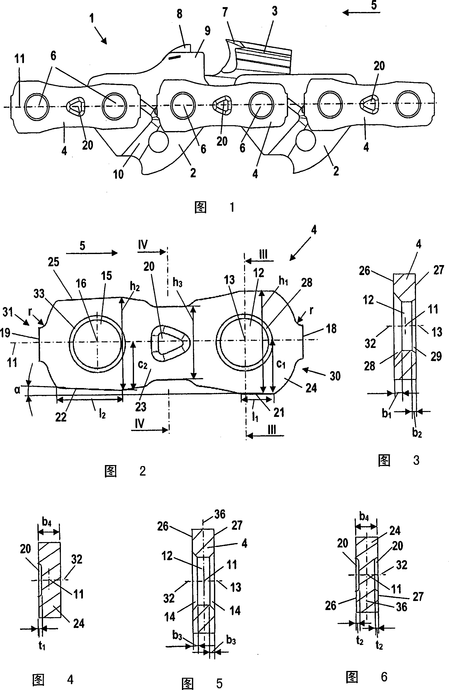
[0025] FIG. 1 shows a section of a saw chain 1 . The saw chain consists of a drive link 2 , a cutting link 3 and a connecting link 4 . The drive chain link 2 , the cutting chain link 3 and the connecting chain link 4 are hingedly connected to each other by rivet bolts 6 . In this case the drive chain links 2 are arranged in the middle, and the connecting chain links 4 are arranged on their outer sides. The rear rivet holes of the driving chain link 2 are respectively connected with the front rivet holes of the connecting chain link 4 , and the front rivet holes of the driving chain link 2 are connected with the rear rivet holes of the connecting chain link 4 . Seen in the chain running direction 5 , instead of a connecting link 4 every two connecting links 4 are provided with a cutting link 3 . In this case, the cutting links 3 are arranged alternately on each longitudinal side of the saw chain 1 . The cutting link 3 has a cutting tooth 7, in front of which a depth limiter ...


PUM


Abstract

A connecting link ( 4, 34 ) for a saw chain ( 1 ) of a motor-driven chain saw has an areal base body ( 24 ) which has two rivet openings ( 12, 15 ). The connecting link ( 4, 34, 44 ) has a longitudinal center axis ( 11 ) which intersects the axes ( 13, 16 ) of rivet openings ( 12, 15 ) and runs in the base body ( 24 ). The functional regions of the connecting links ( 4, 34, 44 ) are mirror symmetrical to planes ( 32, 36 ), which contain the longitudinal center axis ( 11 ), and are unsymmetrical to each plane perpendicular to the longitudinal center axis ( 11 ). In this way, the connecting link ( 4, 34, 44 ) can be arranged on both longitudinal sides of the saw chain ( 1 ).

Description

technical field [0001] The invention relates to a connecting link for a saw chain. The connecting link has a flat base body with two rivet holes and a longitudinal center axis which intersects the axis of the rivet holes and which extends in the base body, wherein the connecting chain The segments are formed asymmetrically with respect to each plane perpendicular to the longitudinal center axis. Background technique [0002] DE 10 209 680 A1 discloses a saw chain with flat connecting links having two rivet holes. The running surfaces have different lengths, so that the connecting links must be installed in the saw chain in the correct position. Such saw chains have a bevel on the outwardly facing side of the rivet holes. The rivet head is partially arranged in this bevel. Since the bevel must face outwards, the connecting link can only be mounted on one longitudinal side of the saw chain. There must be different connecting links for the two longitudinal sides. Such pro...

Claims


Application Information

Patent Timeline
Patent Type & Authority Applications(China)
IPC IPC(8): B27B33/14
CPCB27B33/14B27B33/147Y10T83/909
Inventor A·福克斯
Owner ANDREAS STIHL AG & CO KG
Why Eureka
Try Eureka