Electrically assisted bicycle

An electric assist and bicycle technology, applied to bicycles, electric vehicles, bicycle accessories, etc., can solve the problem of unrealistic switching of regeneration states, and achieve the effects of reducing the number of charging times, comfortable walking performance, and extending the walking distance.

Inactive Publication Date: 2008-02-13
SANYO ELECTRIC CO LTD
View PDF2 Cites 15 Cited by
  • Summary
  • Abstract
  • Description
  • Claims
  • Application Information

AI Technical Summary

Problems solved by technology

And so on, there is a problem that switching to the regenerative state is impractical

Method used


Image

  • Electrically assisted bicycle
  • Electrically assisted bicycle
  • Electrically assisted bicycle

Examples


Embodiment Construction

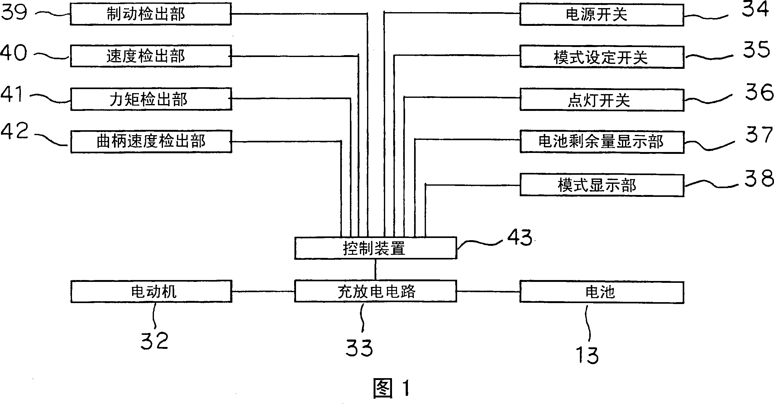
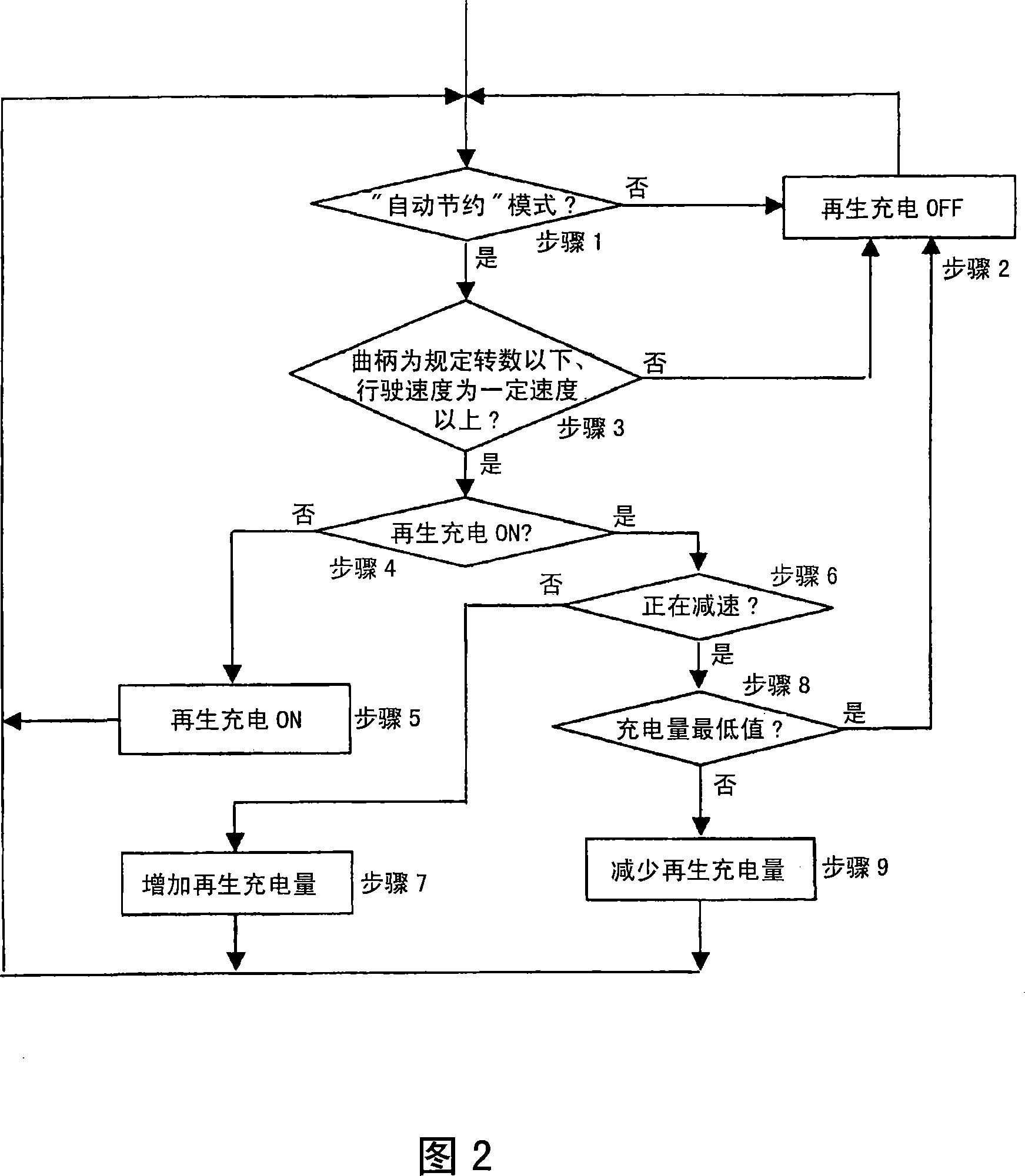
[0022] Next, an embodiment of the present invention will be described in detail with reference to FIGS. 1 to 5 .

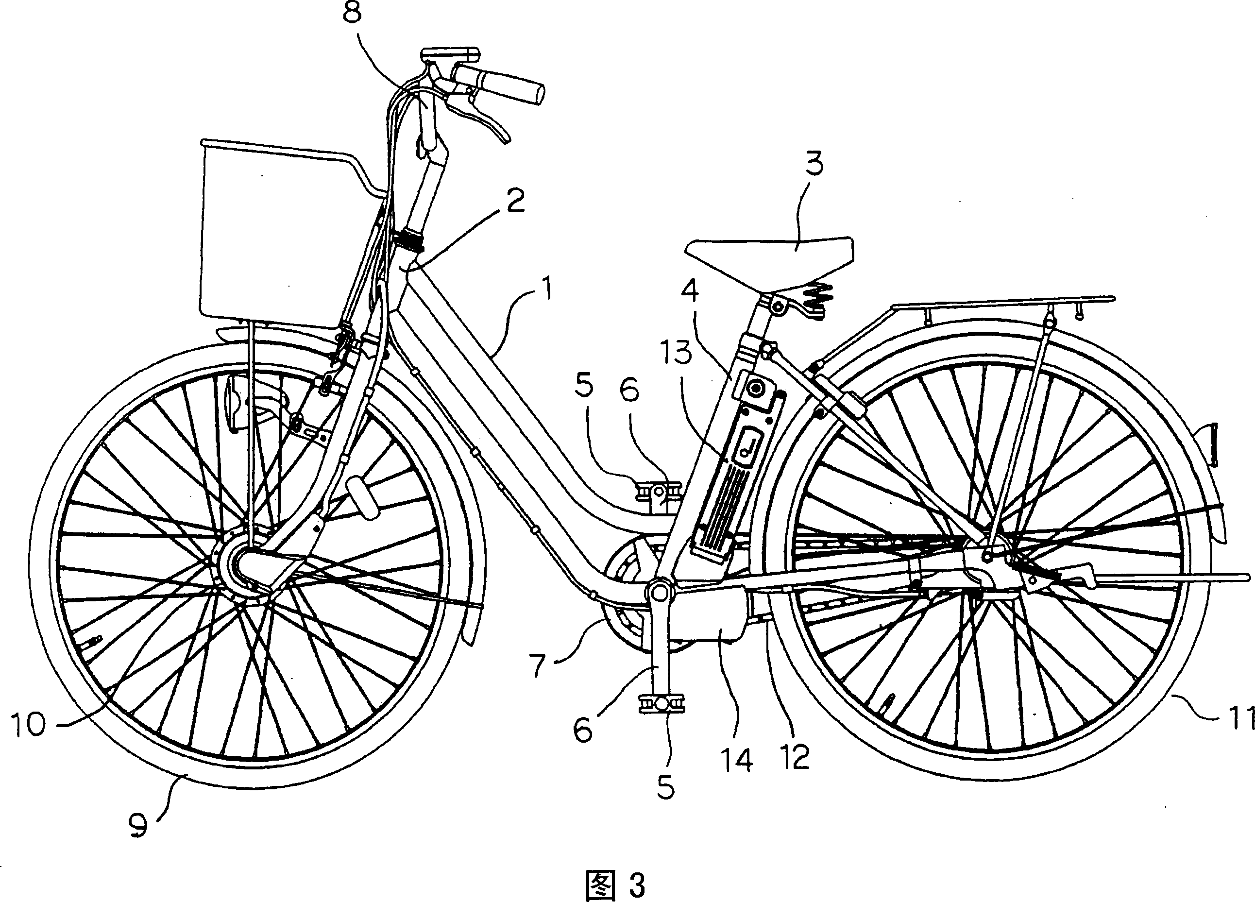
[0023] First, the overall structure of the power-assisted bicycle will be described with reference to FIG. 3 .

[0024] 1 is the vehicle frame, which is connected with the front tube 2 arranged at the front and the seat tube 4 provided under the saddle 3, and the pedal 5 is installed at the connection part connecting the frame 1 and the seat tube 4 The crank 6, and the travel driving device 7 that rotates under the action of the crank 6.

[0025] 8 is the handlebar installed on the upper end of the front tube 2, and 9 is the front wheel installed on the lower end of the front tube 2, which has a wheel hub 10 with a built-in motor not shown in the figure, under the action of the motor , the front wheel 9 is rotationally driven to constitute an electric drive mechanism.

[0026] 11 is a rear wheel, between the rear wheel 11 and the walking drive device 7, a sprock...


PUM


Abstract

The invention provides an electrically assisted bicycle having a simplified construction for reliably effecting a change-over to regenerative generation of power. The bicycle comprises a human power drive mechanism using a human drive force, and an electric drive mechanism adapted to receive power supplied from a battery 13 for driving a motor 32 with a drive force in accordance with a value detected by a torque detector 41 for detecting human torque of the human power drive mechanism. Electric power is produced by regenerative generation when cranks 6 of the human power drive mechanism are rotated with a number of revolutions smaller than is needed for causing the bicycle to run on a level road at a speed detected by a speed detector 40.

Description

technical field [0001] The present invention relates to a motor-assisted bicycle having a human-powered driving mechanism utilizing a human-powered driving force and an electric driving mechanism that drives a motor with a driving force of a human-powered torque of the corresponding human-powered driving mechanism. Background technique [0002] In the prior art, as this type of electrically assisted bicycle, for example, someone has proposed the following scheme: when going downhill, etc., the situation of applying the brake is detected, and the motor is made to generate a braking force (Patent Document 1: Japanese Patent Laid-Open Hei 4- Bulletin No. 100790). [0003] The motor-assisted bicycle of Patent Document 1 only makes the motor generate braking force when braking, and cannot make the motor generate braking force until braking, and cannot put the motor in a regenerative state. [0004] Therefore, someone has proposed the following scheme: detect the speed of the veh...

Claims


Application Information

Patent Timeline
Patent Type & Authority Applications(China)
IPC IPC(8): B62M23/02B62J6/10B62J6/12B62J99/00B62M6/45B62M6/55B62M6/65B62M25/08
CPCB60L2240/423B60L2250/26B60L11/007B60L7/26B60L2240/12B60L15/2009B60L11/1877B60L11/1805B62M6/45B60L7/12B60L2200/12B60L2220/44B60L2250/24B60L11/1861B60L50/20B60L50/52B60L50/66Y02T10/64Y02T10/70Y02T10/72
Inventor 田中建明岛津将博
Owner SANYO ELECTRIC CO LTD
Why Eureka
Try Eureka