Door and window driving and controlling equipment and door and window using the same
A drive control, door and window technology, applied in the field of doors and windows, can solve the problems of not providing electric functions, affecting the visual effect of decoration, and limiting the design of house decoration, etc., and achieve the effect of saving installation space
- Summary
- Abstract
- Description
- Claims
- Application Information
AI Technical Summary
Problems solved by technology
Method used
Image

Examples
Embodiment Construction
[0054] Preferred embodiments of the invention are described below with the aid of the drawings.
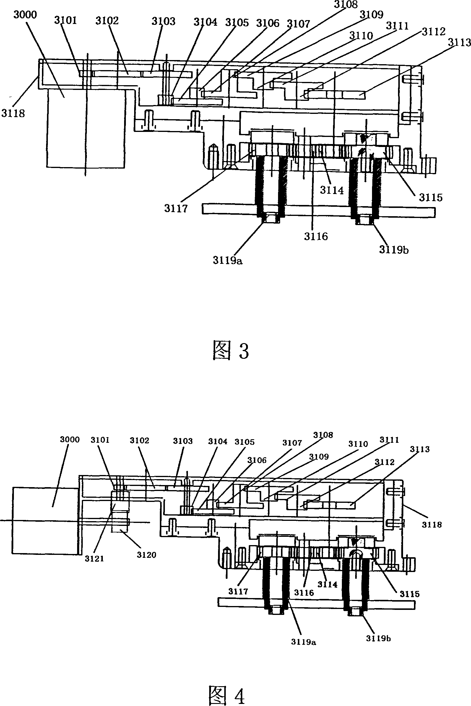
[0055] Fig. 3 is a schematic structural diagram of the door and window driver controller according to the first embodiment of the present invention.
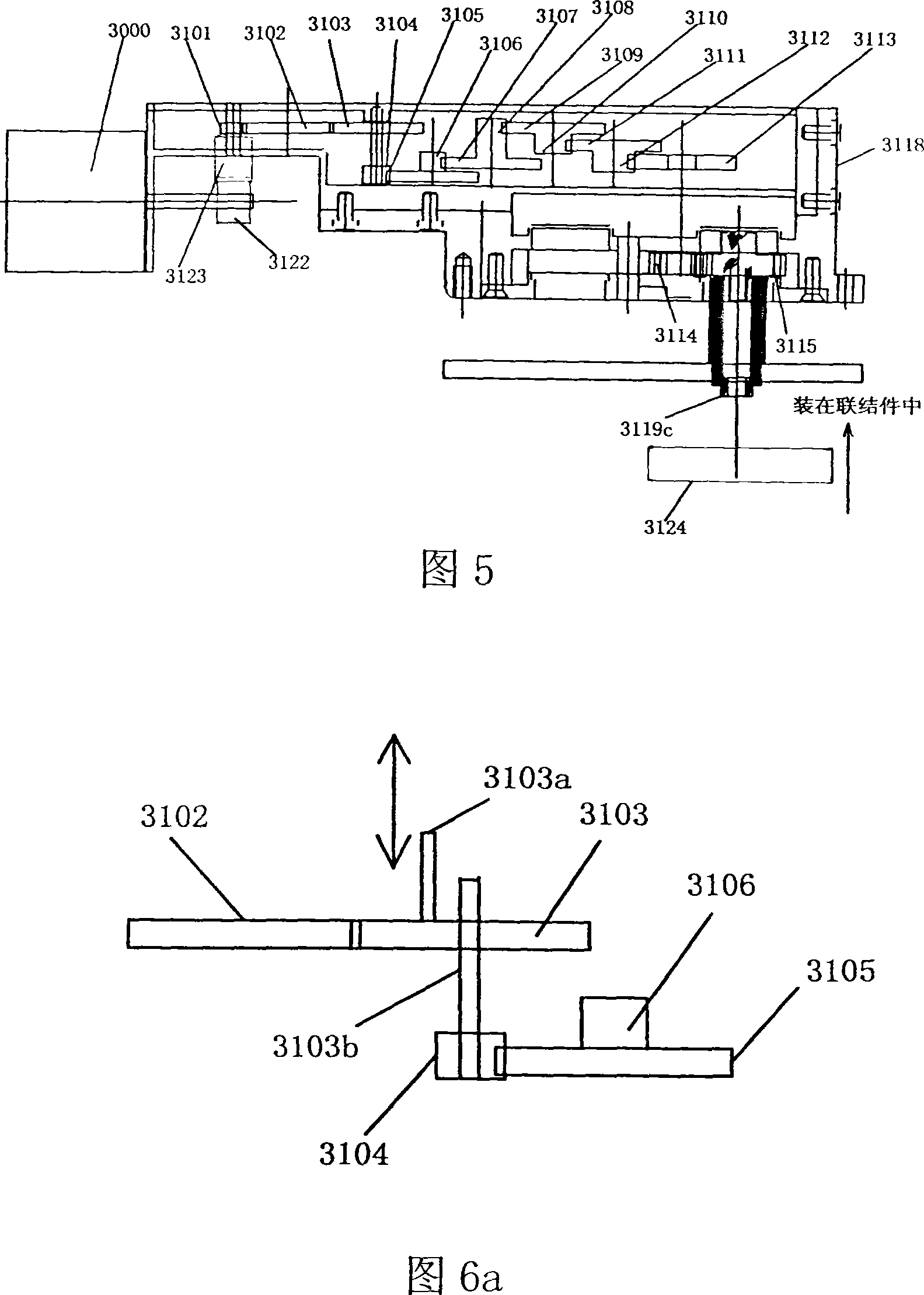
[0056] Referring to Fig. 3, the door and window drive controller includes a motor assembly 3000 and a transmission mechanism 3100, and the transmission mechanism 3100 includes gears 3101-3117, a frame 3118, couplings 3119a and 3119b, and a clutch mechanism as shown in Figs. 6a-6c.
[0057] As shown in FIG. 3 , the motor assembly 3000 is installed on the outer surface of the frame 3118 , which includes a motor whose output shaft extends into the frame, and the gear 3101 is fixedly arranged on the output shaft to rotate with the output shaft. The gears 3101-3117 are all spur gears and are installed in the frame 3118, wherein the gears 3103 and 3104 are a set of coaxial gears, the gears 3105 and 3106 are a set of coaxial gears, and the...
PUM
 Abstract
Description
Claims
Application Information
 - R&D
- Intellectual Property
- Life Sciences
- Materials
- Tech Scout
- Unparalleled Data Quality
- Higher Quality Content
- 60% Fewer Hallucinations
Browse by: Latest US Patents, China's latest patents, Technical Efficacy Thesaurus, Application Domain, Technology Topic, Popular Technical Reports.
© 2025 PatSnap. All rights reserved.Legal|Privacy policy|Modern Slavery Act Transparency Statement|Sitemap|About US| Contact US: help@patsnap.com