Clock signal output apparatus and control method of same, and electric apparatus and control method of same

A clock signal output, electronic equipment technology, applied in electronic timers, clocks, master clocks, etc., can solve problems such as poor frequency accuracy, temperature changes in oscillation frequency, etc.

Inactive Publication Date: 2010-12-08
SEIKO EPSON CORP
View PDF11 Cites 0 Cited by
  • Summary
  • Abstract
  • Description
  • Claims
  • Application Information

AI Technical Summary

Problems solved by technology

[0006] However, the conventional temperature-compensated crystal oscillator adopts a structure that temperature-compensates the temperature characteristic of the crystal having the third-order characteristic according to the temperature characteristic of the capacitance having the second-order characteristic, so the oscillation frequency changes with temperature
In addition, this type of crystal oscillator changes the oscillation frequency over a long period of time due to the aging characteristics of the crystal, and its frequency accuracy is poor compared to atomic oscillators.

Method used


Image

  • Clock signal output apparatus and control method of same, and electric apparatus and control method of same
  • Clock signal output apparatus and control method of same, and electric apparatus and control method of same
  • Clock signal output apparatus and control method of same, and electric apparatus and control method of same

Examples


no. 1 Embodiment approach

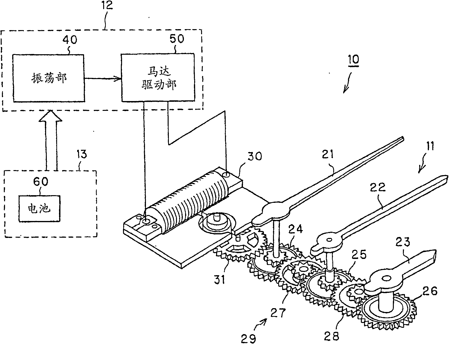
[0051] figure 1 It is a block diagram showing the structure of a watch according to an embodiment of the present invention. The wristwatch (electronic timepiece) 10 is configured to include a hand movement mechanism 11 and a drive unit 12 constituting a timepiece module, and a power supply unit 13 for supplying operating power to the timepiece module.

[0052] The hand movement mechanism 11 constitutes a time display unit that drives the second hand 21, the minute hand 22, and the hour hand 23 to display the time. As shown in the figure, it has a gear train 29 that combines the second wheel 24, the second wheel 25 and the hour The wheels 26 are connected to each other via intermediate wheels 27 and 28 in linkage. One end of the second hand 21 is mounted on the rotating shaft of the second wheel 24, one end of the minute hand 22 is mounted on the rotating shaft of the second wheel 25, and one end of the hour hand 23 is mounted on the rotating shaft of the hour wheel 26. The drivi...

no. 2 Embodiment approach

[0073] The watch 10A of the second embodiment is as Figure 8 As shown, there is a sensor unit 65 having a first detection unit (reference oscillator influence information detection unit) 70 that detects the influence of the operation of the crystal oscillator (reference oscillator) 41 etc. The first information (reference oscillator influence information); and the second detection unit (high-precision oscillator influence information detection unit) 80 that detects the second influence on the operation of the atomic oscillator (high-precision oscillator) 42 etc. Information (High-precision oscillator affects information). Hereinafter, the same reference numerals are given to the structures substantially the same as those of the first embodiment, detailed descriptions are omitted, and different parts are described in detail.

[0074] The first detection unit 70 includes a temperature detection unit 71 that detects temperature (including outside air temperature); a voltage detecti...

no. 3 Embodiment approach

[0087] The watch 10B of the third embodiment is as Picture 11 As shown, there is a temperature detection unit 71 that detects temperature (reference oscillator influence information), and this temperature detection unit 71 is connected to the intermittent time management unit 47 of the oscillation unit 40. The intermittent time management unit 47 has a counter 47a1 for timing the update period P1 of the correction data and a counter 47b2 for timing the temperature detection interval P2, and is configured to be capable of timing the update period P1 and the temperature detection interval P2.

[0088] And, in the memory 46a, such as Picture 12 As shown, correction data D1(k) (k=temperature) corresponding to each temperature is stored. In addition, the figure shows a case where the correction data D1(k) is set every 1 degree. However, from the viewpoint of reducing the amount of data, it can be set roughly every 5 degrees, for example. In this case, the The correction data D1(n) o...


PUM


Abstract

Provided are a clock signal outputting device and its control method, and an electronic device and its control method, which can enhance the precision of a clock signal while avoiding an increase in the entire power consumption even if a highly precise oscillator of a relatively high power consumption is used. The clock signal output device includes a quartz oscillator (41) for generating a reference clock signal (CL1), and generates and outputs an outputted clock signal (CL0) of a predetermined frequency from the reference clock signal (CL1). The clock signal output device further includes an atomic oscillator (42) for generating a clock signal (CL2) of a higher precision than that of the quartz oscillator (41), an intermittent time managing unit (47) for driving the atomic oscillator (42) intermittently, and a correction unit (46) for acquiring correction data to correct the displacement of the outputted clock signal (CL0) with reference to the clock signal (CL2), each time the atomic oscillator (42) is driven, thereby to correct the outputted clock signal (CL0) on the basis of that correction data.

Description

Technical field [0001] The present invention relates to a clock signal output device that has a reference oscillator that generates a reference clock signal and generates and outputs a clock signal for output of a predetermined frequency based on the reference clock signal, and a control method thereof, an electronic device and a control method thereof. Background technique [0002] Conventionally, electronic timepieces include electronic timepieces that divide the frequency of a reference clock signal output from a reference oscillator to generate, for example, a 1 Hz signal, and time the time based on the 1 Hz signal. This type of electronic timepiece is known as an annual difference timepiece. The annual difference timepiece uses a temperature-compensated crystal oscillator (Temperature Compensated Crystal Oscillator) as a reference oscillator to achieve an annual difference within ± tens of seconds (for example, Patent Document 1). In recent years, standard oscillators using ...

Claims


Application Information

Patent Timeline
Patent Type & Authority Patents(China)
IPC IPC(8): G04G3/00G04G3/04
CPCG04C13/00G04F5/14G04G3/00
Inventor 关重彰井上胜豊
Owner SEIKO EPSON CORP
Why Eureka
Try Eureka