Clubfoot angle adjusting mechanism of glasses frame

A technology of angle adjustment and spectacle frame, applied in the directions of glasses/goggles, optics, instruments, etc., it can solve the problems of long waiting time for customers, little freedom of design, and inability to assemble, so as to meet the large market demand, simple and rapid adjustment , the effect of high application value

Inactive Publication Date: 2008-02-27
上海野尻光学有限公司
View PDF2 Cites 2 Cited by
  • Summary
  • Abstract
  • Description
  • Claims
  • Application Information

AI Technical Summary

Problems solved by technology

Therefore, customers have to wait for a long time, and manual operators are required to have a high degree of skill, which cannot be easily assembled.
[0004] Especially in a spectacle frame using a superelastic alloy for temples as described in Japanese Patent Publication No. 7-56537 (claim 1, claim 2), during use, the shape afte...

Method used


Image

  • Clubfoot angle adjusting mechanism of glasses frame
  • Clubfoot angle adjusting mechanism of glasses frame
  • Clubfoot angle adjusting mechanism of glasses frame

Examples


Embodiment 1

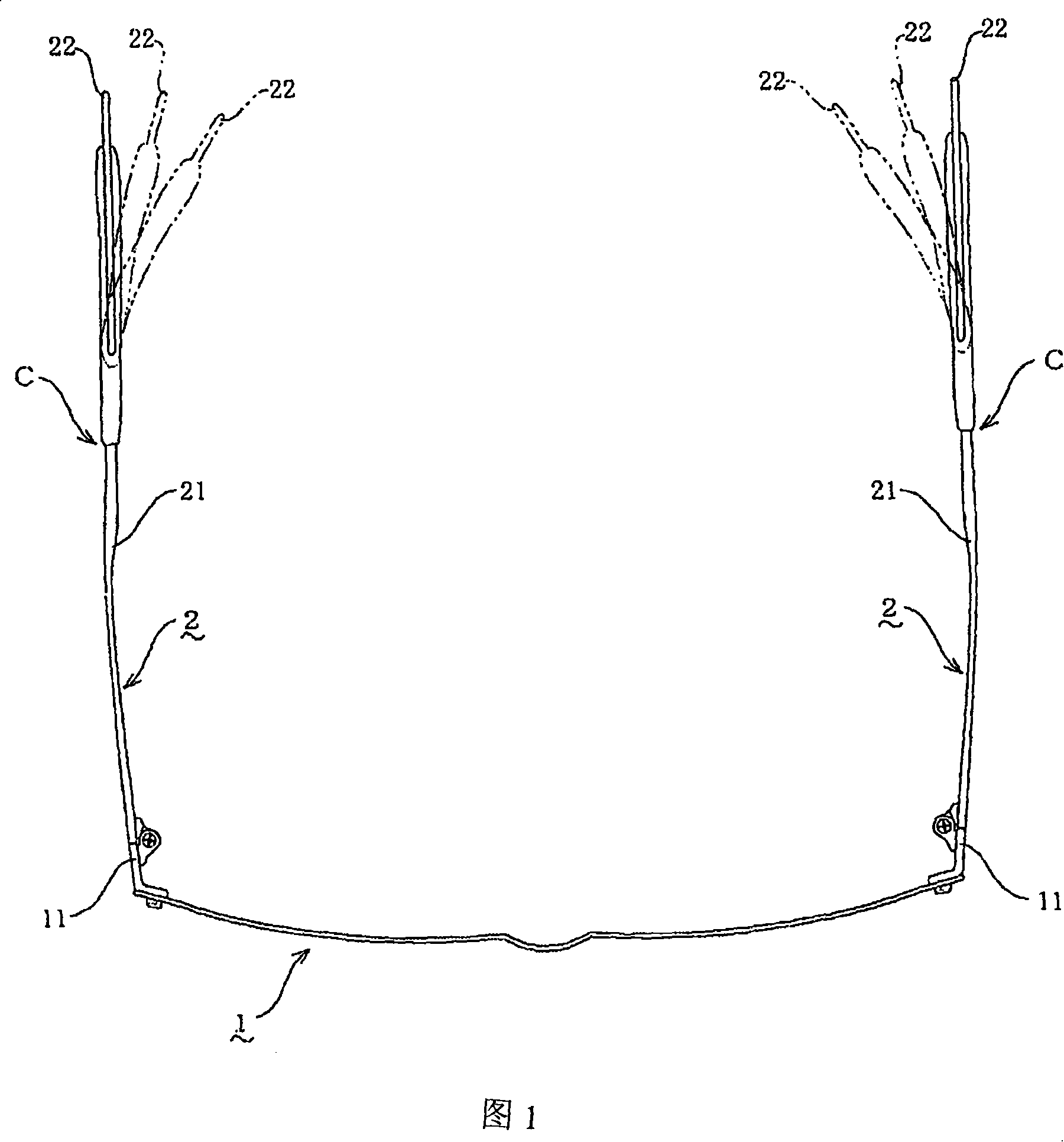
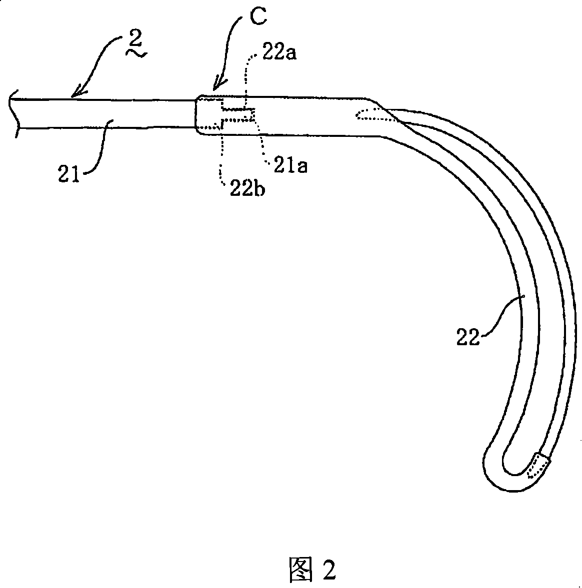
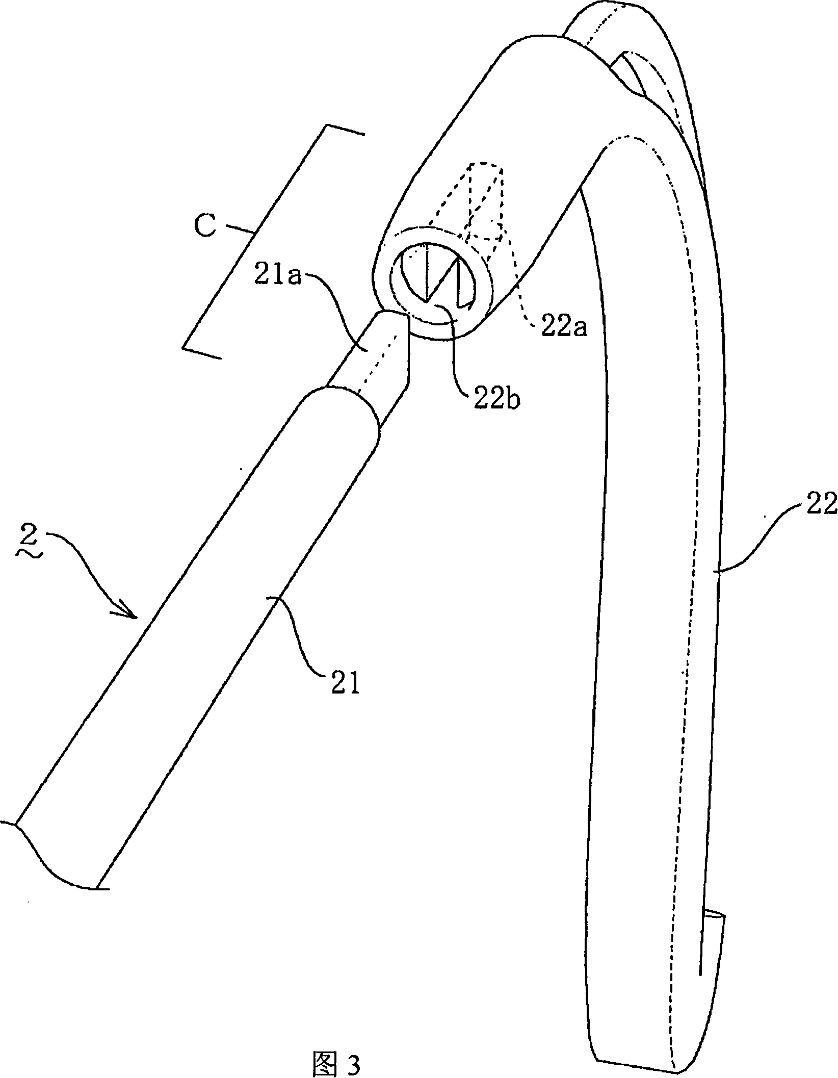
[0023] Referring to Figures 1 to 4, 1 is the front frame, and 2 is the temple. The two ends of the front frame 1 that can be installed to correct the wearer's eyesight or protect the retina are equipped with a pair of temples 2 extending backward, and the temples 2 can be used to clamp the left and right sides of the wearer's head. The front frame 1 is kept on the position in front of the wearer's eyes (see Fig. 1, Fig. 2). The side bars 21 of the front frame 1 and the temple 2 are constituted as metal frames, and the front ends of the side bars 21, 21 of a pair of temples 2 are connected to the rear ends of the left and right connecting parts 11 fixed on the two ends of the front frame 1 with hinges respectively. . The temple 2 that is connected with the extended end 21a of the curved foot 22 and the side bar 21 as a whole, the curved foot 22 is framed near the periphery of the wearer's ear base, and clamps the wearer's head from the left and right sides.

[0024] The joint...

Embodiment 2

[0030] Referring to Fig. 5, Embodiment 2 is the same as Embodiment 1, the difference is that in this embodiment, the joint part C of the side bar 21 of the temple 2 and the bending foot 22 is provided with a mutual fitting structure, so as to bend The connecting end 22c of the foot 22 is fitted into the insertion opening 21b on the rear end of the side bar for angle adjustment, and can be adjusted according to the inclination of the wearer's head near the base of the ear (refer to FIG. 5 ). The connecting end 22c of the bent foot 22 of the temple 2 is tenon-shaped, and a variety of bent feet 22 with tenon-shaped connecting ends 22c with different axial angles relative to the bent foot are prefabricated, and a suitable one is selected according to needs. The bent feet 22 are replaced to form temples 2 suitable for both sides of the wearer's head.

[0031] In this way, as long as the bent foot 22 of the temple 2 is replaced, it can be easily adjusted to the spectacle frame suita...

Embodiment 3

[0033] Embodiment 3 is the same as Embodiment 2, except that in this embodiment, the extended end 21a of the side bar 21 of the temple 2 is a gear with a section that can be inserted into the interface 22a of the bent foot 22 at multiple axial angles. like tenon shape (see Figure 6). In this way, it is not necessary to prepare various side bars 21 or bent legs 22 with different axial angles of the concavo-convex portion of the temple 2 in advance, so the use is more convenient and the production cost can be reduced.

[0034] The material of the temple 2 can be high-strength beta titanium alloy, etc., as long as it is easy to process, metal materials other than nickel nickel can also be used, and synthetic resin materials such as acetate resin can also be used.

[0035] In addition, on the joint portion C between the side rod extension end 21a of the temple 2 and the bent leg 22, see Fig. 7a, Fig. 7b, and Fig. 7c, the interface 22a can also have a variety of bent legs 22 with d...


PUM


Abstract

The present invention relates to a clubfoot angle adjusting device of the glass frame, the side shoring (2) respectively includes a side lever (21) and a clubfoot (22), the clubfoot (22) which is connected with the extending end part (21a) of the side lever (21) is supported at the circumference of the ear root of the wearer and clamps the two sides of the head from the left and right two sides, and a structure which inserts with each other is arranged at the connecting part (C) between the extending end part (21a) of the side lever and the clubfoot (22) in order to do angle adjusting to the interface (22a) between the extending end part (21a) and the clubfoot (22), and the clubfoot is made to the structure that the clubfoot can be adjusted according to the inclining of the two sides of the head near the circumference of the ear root part of the wearer. The device can be simply do installing and adjusting to fit the head width of the wearer even if the space between the left and the right side shoring is bigger relative to the head width of the wearer, the installing is simple and convenient and the external appearance is excellent.

Description

technical field [0001] The present invention relates to the improvement of spectacle frames, and more specifically, relates to the fact that even if the distance between the left and right temples is large relative to the width of the wearer's head, it can be easily assembled and adjusted to suit the width of the wearer's head and has an excellent appearance. The angle adjustment mechanism of the bent foot of the spectacle frame. Background technique [0002] As we all know, on the spectacle frame, the curved leg hanging on the ear base is arranged at the rear of the temple, and when the spectacle frame is assembled and adjusted, the curved leg is bent and deformed in line with the inclination of the two sides of the head, so that the The wearer has a more comfortable feeling. [0003] The temple structure of the spectacle frame in the past is known to have a structure in which the metal core extending to the rear of the temple is inserted into the hollow part of the bent p...

Claims


Application Information

Patent Timeline
IPC IPC(8): G02C5/14
Inventor 水口秀则
Owner 上海野尻光学有限公司
Why Eureka
Try Eureka