Supercharge Your Innovation With Domain-Expert AI Agents!

Contraposition structure of plasma display panel

A display panel and plasma technology, applied in the direction of solid cathode parts, discharge tube/lamp manufacturing, electrical components, etc., can solve the problems of increasing alignment error, alignment mark deformation, and deviation from the original position, etc.

Inactive Publication Date: 2010-06-02
AU OPTRONICS CORP
View PDF5 Cites 0 Cited by
  • Summary
  • Abstract
  • Description
  • Claims
  • Application Information

AI Technical Summary

Problems solved by technology

However, the circular or cross-shaped alignment marks on the rear substrate are formed at the same time as the address electrodes are formed. The alignment marks need to go through multiple thermal manufacturing processes due to the dielectric layer and barrier rib structure, resulting in alignment marks Deformation or deviation from the original position, which greatly increases the alignment error

Method used


Image

  • Contraposition structure of plasma display panel
  • Contraposition structure of plasma display panel
  • Contraposition structure of plasma display panel

Examples


Embodiment Construction

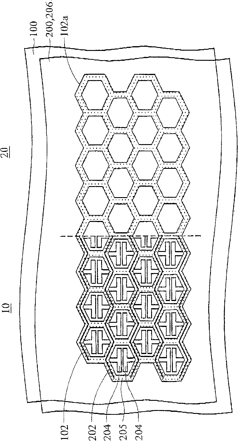
[0032] see figure 1 , the plasma display panel includes a rear substrate 100 and a front substrate 200 oppositely disposed. The rear substrate 100 and the front substrate 200 are divided into a display area 10 and a non-display area 20 .

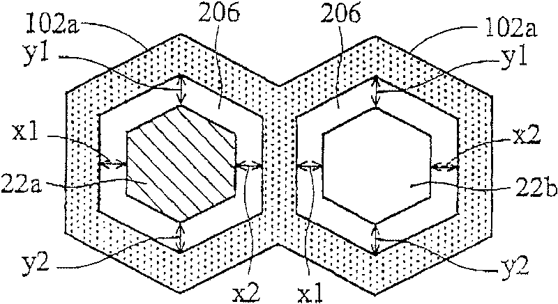
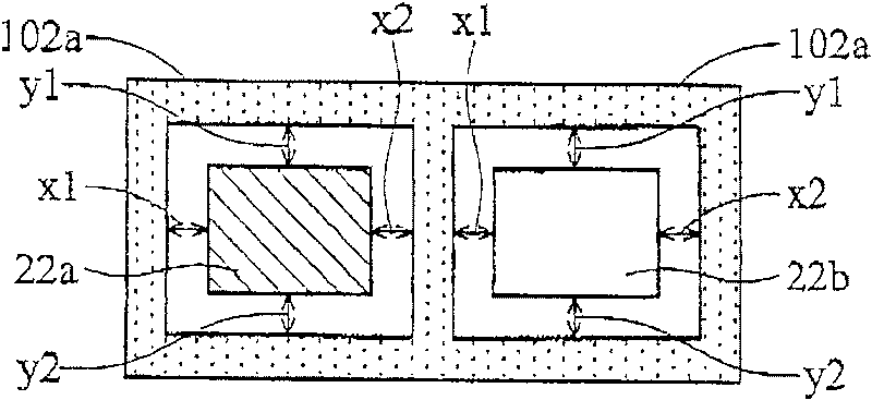
[0033] The hexagonal barrier rib structures 102 and 102a are respectively formed on the display area 10 and a non-display area 20 of the rear substrate 100 . Each hexagonal barrier structure is adjacent to each other to form a honeycomb barrier structure, such as figure 1 shown. It should be noted that the hexagonal barrier structures 102 and 102a can be closed or have openings at the corners for gas injection and exhaust. In the display region 10 , the space defined by the hexagonal barrier rib structure 102 serves as a discharge space. A plurality of address electrodes (not shown) are parallel to each other and disposed on the rear substrate 100 below the hexagonal barrier rib structures 102 and 102a.

[0034] A plurality of auxilia...


PUM


Abstract

This invention has revealed a plasma display panel (PDP) with a counterpart structure. This counterpart structure is placed outside the display area of the plasma display panel, including: post-substrate; one first-counterpart pattern. This pattern is set up in the post-substrate outside the display area. It includes a rectangle block of addressable electrode; a front-substrate. It is installed atthe relative top of the post-substrate; and the second pattern with the shape of rectangle-ring. It is located in the front-substrate which is outside the display area and corresponds to the space around this rectangle block.

Description

[0001] This application document is a divisional application of No. 200410034643.4 patent application for invention submitted on April 19, 2004. technical field [0002] The invention relates to a plasma display panel (PDP), in particular to an alignment structure for assembling the plasma display panel. Background technique [0003] Recently, different types of flat panel displays, such as liquid crystal displays (LCDs) and plasma display panels (PDPs), have been continuously developed to gradually replace conventional cathode ray tube (CRT) type displays. In the technology of the plasma display panel, ultraviolet light is used to excite three primary colors (RGB) phosphors and generate visible light. The advantages of the plasma display panel are large display area, wide viewing angle, and high brightness. [0004] Figure 11 A conventional plasma display panel structure is shown, which includes: a rear glass substrate 300 and a front glass substrate 308, which are separa...

Claims


Application Information

Patent Timeline
Patent Type & Authority Patents(China)
IPC IPC(8): H01J9/00H01J17/02H01J17/04H01J17/16H01J17/49
Inventor 万祥文苏耀庆
Owner AU OPTRONICS CORP
Features
  • R&D
  • Intellectual Property
  • Life Sciences
  • Materials
  • Tech Scout
  • Unparalleled Data Quality
  • Higher Quality Content
  • 60% Fewer Hallucinations
Learn More