Alignment structure for plasma display panel

a technology for assembling and displaying panels, applied in the direction of identification means, instruments, electric discharge tubes/lamps, etc., can solve the problems of increasing alignment errors, and achieve the effect of reducing alignment errors

Inactive Publication Date: 2005-10-06
AU OPTRONICS CORP
View PDF2 Cites 14 Cited by
  • Summary
  • Abstract
  • Description
  • Claims
  • Application Information

AI Technical Summary

Benefits of technology

[0007] Accordingly, an object of the present invention is to provide a novel alignment structure for a plasma display panel (PDP) to reduce alignment errors between the rear and front substrates of the PDP.

Problems solved by technology

As a result, the alignment mark deforms or shifts from the original position, significantly increasing alignment errors.

Method used


Image

  • Alignment structure for plasma display panel
  • Alignment structure for plasma display panel
  • Alignment structure for plasma display panel

Examples


Embodiment Construction

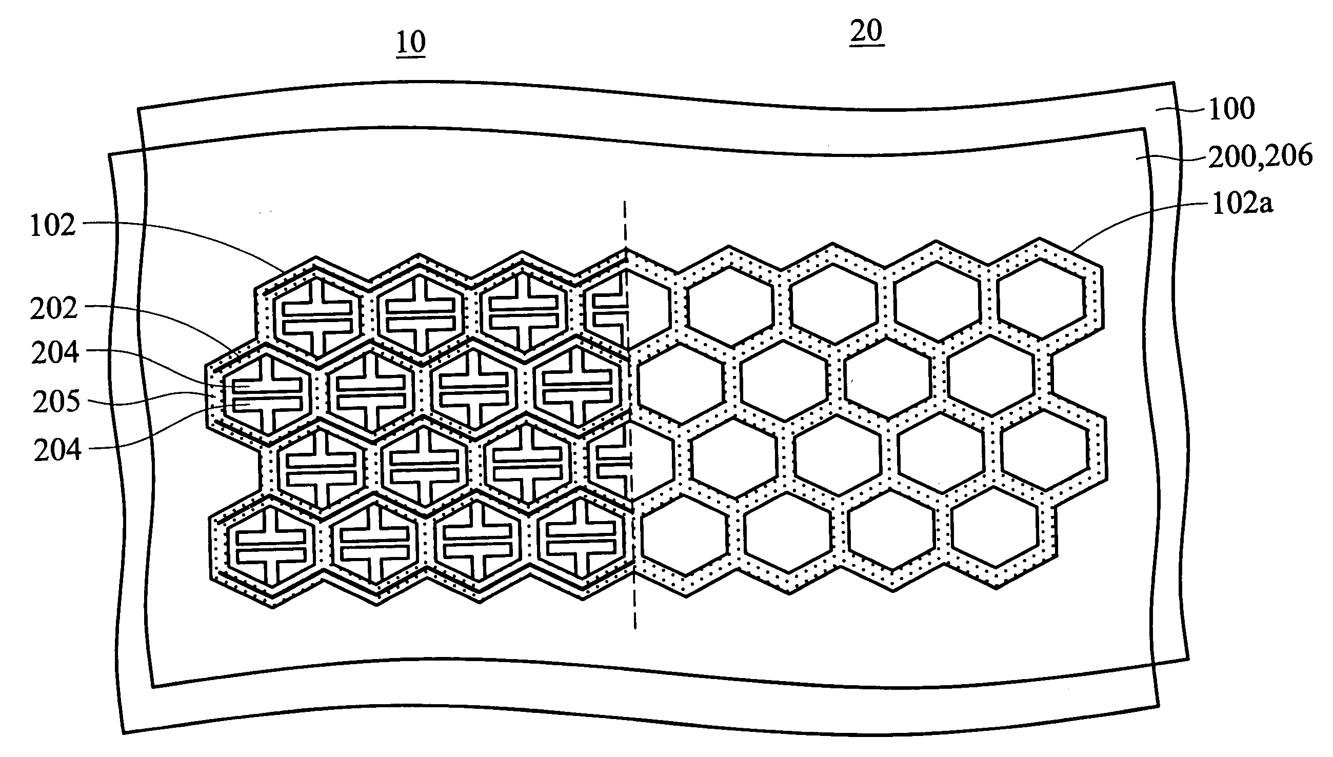
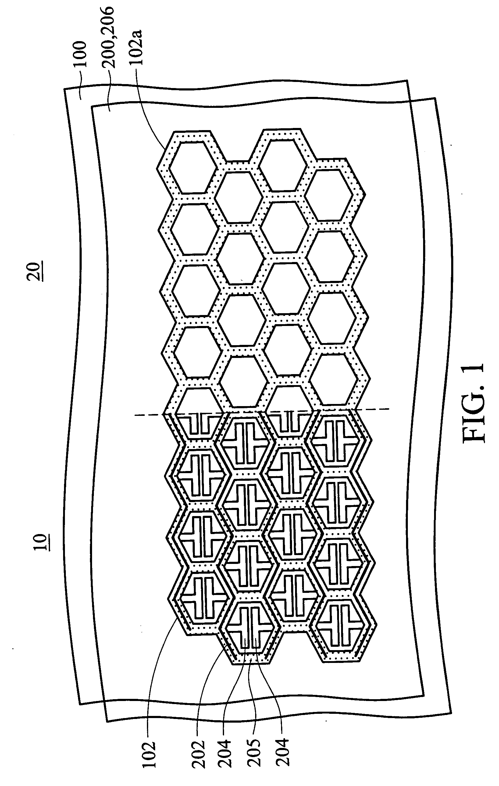
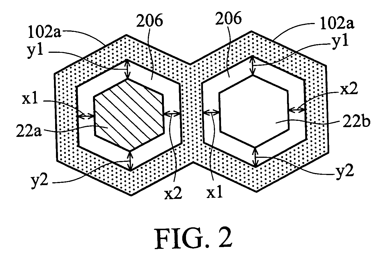
[0028] In FIG.1, the plasma display panel (PDP) comprises a rear substrate 100 and a front substrate 200 opposite to each other. The rear substrate 100 and the front substrate 200 are divided into a display area 10 and a non-display area 20.

[0029] Hexagonal rib structures 102 and 102a are respectively formed on the display area 10 and the non-display area 20 of the rear substrate 100, with each hexagonal rib structure adjacent to constitute a honeycombed rib structure, as shown in FIG. 1. It is noted that the hexagonal rib structures 102 and 102a may be enclosed or have openings at corners for injecting and exhausting gas. The spaces defined by the hexagonal rib structures 102 on the display area 10 act as discharge cells. A plurality of address electrodes (not shown) parallel to each other is disposed on the rear substrate 100 under the hexagonal rib structures 102 and 102a.

[0030] A plurality of bus electrodes 202, such as Cr—Cu alloy, overlies the front substrate 200 and corresp...


PUM


Abstract

A plasma display panel (PDP) with alignment structure. A first alignment pattern is disposed on a rear substrate and formed by a rib structure. A second alignment pattern is disposed on a front substrate disposed opposite, over the rear substrate and corresponds to a space defined by the first alignment pattern. The first and second alignment patterns are disposed outside of the display area of the plasma display panel.

Description

BACKGROUND OF THE INVENTION [0001] 1. Field of the Invention [0002] The present invention relates in general to a plasma display panel (PDP), and more particularly, to an alignment structure for assembling a plasma display panel. [0003] 2. Description of the Related Art [0004] Recently, a variety of flat panel displays, such as liquid crystal display (LCD) and plasma display panel (PDP) have been intensively developed to replace cathode ray tube (CRT) displays. In PDP technology, ultraviolet light is emitted to excite RBG phosphors and produce visible light. The advantages of the PDP include a large display area, wide viewing angle, and intense brightness. [0005]FIG. 11 illustrates a conventional plasma display panel structure. The PDP comprises a rear glass substrate 300 and a front glass substrate 308 spaced apart from each other. A plurality of address electrodes (data electrodes) 302 is disposed on the rear substrate 300 and faces the front substrate 308. A dielectric layer 304 ...

Claims


Application Information

Patent Timeline
Patent Type & Authority Applications(United States)
IPC IPC(8): G09F9/30H01J9/00H01J9/18H01J9/24H01J9/46H01J17/49H02K5/26
CPCH01J9/185H01J9/241H01J11/12H01J11/34
Inventor WAN, HSIANG-WENSU, YAO-CHING
Owner AU OPTRONICS CORP
Why Eureka
Try Eureka