Self-reference interference alignment system for photoetching equipment

A technology of self-referencing interference and alignment system, which is applied in microlithography exposure equipment, optics, photoplate making process of pattern surface, etc., and can solve problems such as alignment errors and affecting signal quality

Active Publication Date: 2013-10-23
SHANGHAI MICRO ELECTRONICS EQUIP (GRP) CO LTD
View PDF16 Cites 16 Cited by
  • Summary
  • Abstract
  • Description
  • Claims
  • Application Information

AI Technical Summary

Problems solved by technology

[0005] In this invention, due to the fluctuation of the light intensity irradiated on the mark (the energy change over time, mainly caused by the fluctuation of the output light intensity of the laser, the energy fluctuation caused by phase modulation and

Method used


Image

  • Self-reference interference alignment system for photoetching equipment
  • Self-reference interference alignment system for photoetching equipment
  • Self-reference interference alignment system for photoetching equipment

Examples


Embodiment Construction

[0024] In the following, preferred embodiments according to the present invention will be described in detail with reference to the accompanying drawings. For the convenience of describing and highlighting the present invention, relevant components existing in the prior art are omitted from the drawings, and the description of these known components will be omitted.

[0025] The purpose of the present invention is to provide an improved self-referencing interference alignment system, which can effectively eliminate the signal quality deterioration caused by the light intensity fluctuation (that is, optical noise) irradiated on the mark, and obtain better alignment signals , thereby improving the repeatability of the alignment.

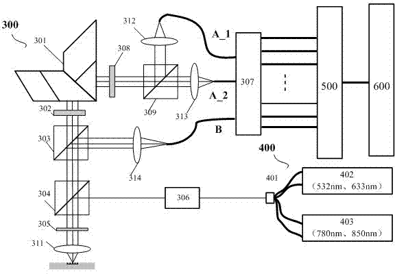
[0026] Such as image 3 As shown, the alignment system provided by the present invention includes a laser light source module 400 , an optical module 300 , an electronic acquisition module 500 , and a software module 600 . Wherein, the laser light so...


PUM


Abstract

The invention discloses a self-reference interference alignment system for photoetching equipment. The system comprises a laser light source module, an optical module, a signal acquisition module and a processing module, wherein the laser light source module is used for providing illumination beams; the optical module is used for marking the illumination beams to form a diffraction optical signal; the signal acquisition module is used for processing the optical signal to acquire a light intensity signal; the processing module is used for processing the light intensity signal to acquire an alignment position by combining position data of a workpiece table; the optical module comprises a first optical channel and a second optical channel; an optical signal in the second optical channel is processed to be used for eliminating optical noises in the first optical channel.

Description

technical field [0001] The invention relates to the field of integrated circuit equipment manufacturing, in particular to a self-referencing interference alignment system for photolithography equipment. Background technique [0002] In the manufacturing process of semiconductor IC integrated circuits, a complete chip usually needs to undergo multiple photolithography exposures before it can be completed. Except for the first photolithography, the photolithography of other levels must be accurately positioned before exposure, so as to ensure the correct relative position between the graphics of each layer. Instant overlay accuracy. Normally, the overlay accuracy is 1 / 3 to 1 / 5 of the resolution index of the lithography machine. For a 100nm lithography machine, the overlay accuracy index is required to be less than 35nm. Overlay accuracy is one of the main technical indicators of a projection lithography machine, and the alignment accuracy between the mask and the silicon waf...

Claims


Application Information

Patent Timeline
IPC IPC(8): G03F9/00G03F7/20
Inventor 李运锋朱正平宋海军
Owner SHANGHAI MICRO ELECTRONICS EQUIP (GRP) CO LTD
Why Eureka
Try Eureka