LITHOGRAPHY ALIGNMENT SYSTEM AND METHOD USING nDSE-BASED FEEDBACK CONTROL

a technology of feedback control and alignment system, applied in the field of semiconductors, to achieve the effect of reducing alignment error and reducing alignment error

Inactive Publication Date: 2008-04-17
HEWLETT PACKARD DEV CO LP
View PDF12 Cites 14 Cited by
  • Summary
  • Abstract
  • Description
  • Claims
  • Application Information

AI Technical Summary

Benefits of technology

[0009]In other embodiments of the present invention, a method of disturbance compensation during contact lithography is provided. The method of disturbance compensation comprises acquiring a first image of a patterning tool and a substrate being patterned by the contact lithography. The first image is acquired after establishing an alignment between the patterning tool and the substrate. The method of disturbance compensation further comprises acquiring a second image of the patterning tool and the substrate after a disturbance of the alignment, the disturbance degrading the alignment. The method of disturbance compensation further comprises estimating an alignment error induced by the disturbance using nanoscale displacement sensing and estimation (nDSE) applied to the first image and the second image. The method of disturbance compensation further comprises adjusting a relative position of the patterning tool and the substrate to reduce the alignment error.
[0010]In other embodiments of the present invention, a contact lithography alignment system is provided. The contact lithography alignment system comprises an optical sensor that produces an image of one or more objects being aligned. The contact lithography alignment system further comprises a feedback processor providing nanoscale displacement sensing and estimation (nDSE). The feedback processor receives the image from the optical sensor and determines an alignment error from the image using the nDSE. The alignment error is relative to an initial alignment of the objects. The contact lithography alignment system further comprises a position controller that adjusts relative positions of one or more of the objects to reduce the alignment error determined by the feedback processor.

Problems solved by technology

The alignment error is relative to an initial alignment of the objects.

Method used


Image

  • LITHOGRAPHY ALIGNMENT SYSTEM AND METHOD USING nDSE-BASED FEEDBACK CONTROL
  • LITHOGRAPHY ALIGNMENT SYSTEM AND METHOD USING nDSE-BASED FEEDBACK CONTROL
  • LITHOGRAPHY ALIGNMENT SYSTEM AND METHOD USING nDSE-BASED FEEDBACK CONTROL

Examples


Embodiment Construction

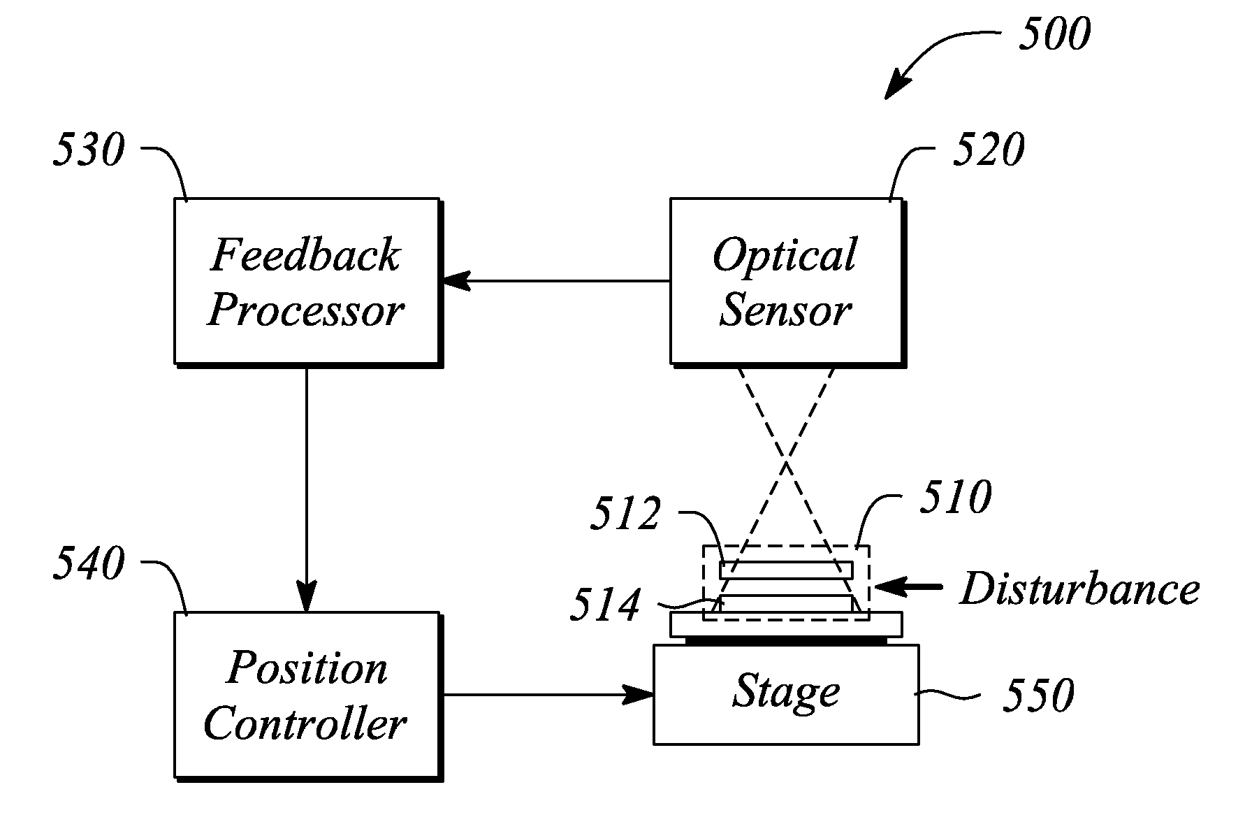
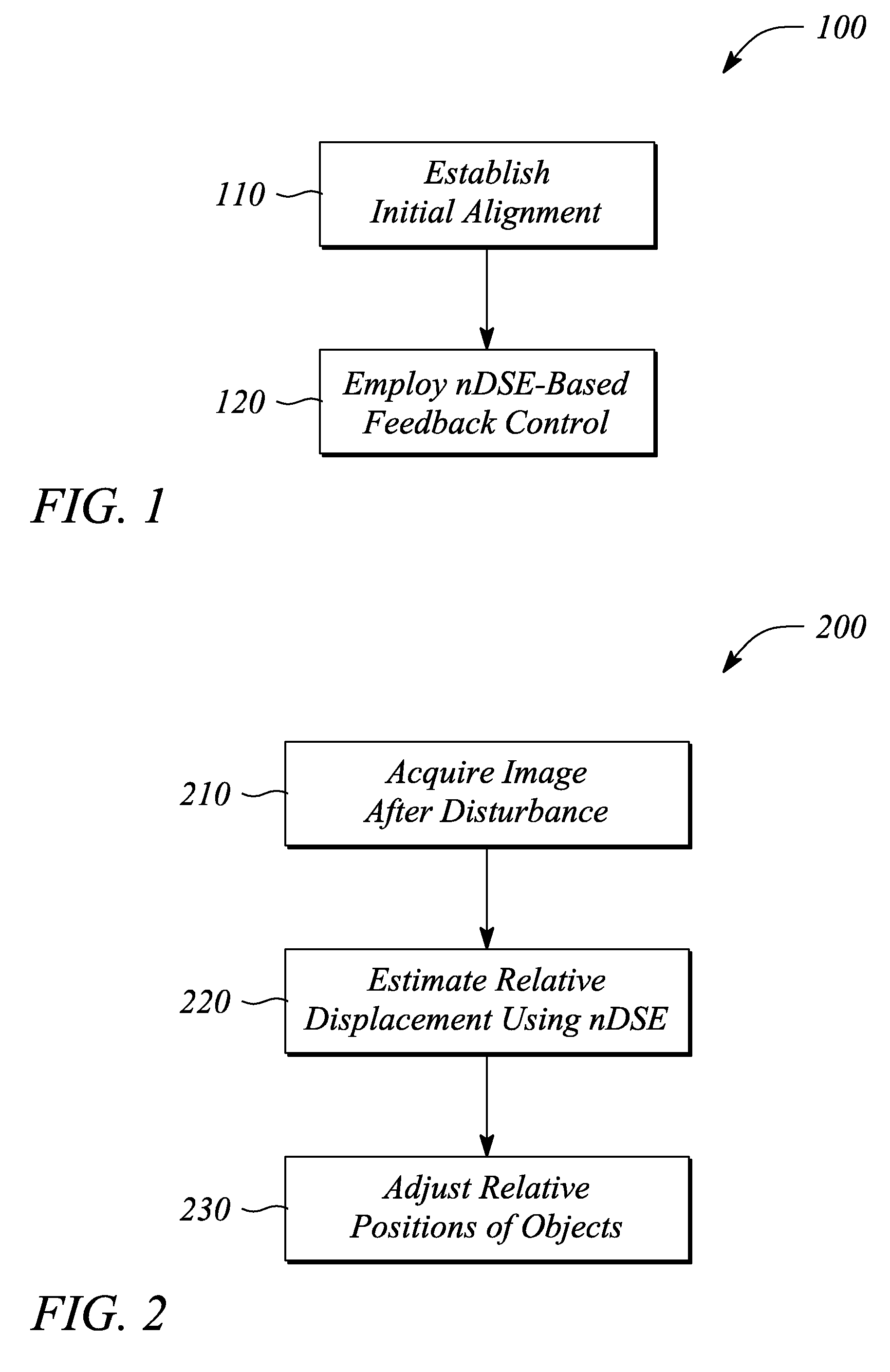
[0020]The embodiments of the present invention facilitate employing lithography to apply a pattern to a substrate (i.e., “patterning a substrate”). In some embodiments, the lithography comprises contact lithography involving a contact between a patterning tool and a substrate. In various embodiments, the present invention employs nanoscale displacement sensing and estimation (nDSE) to estimate and reduce and effect of a disturbance on an alignment associated with the lithography. The nDSE is image-based according to the present invention. In particular, the present invention employs images of aligned objects acquired before and after the disturbance. In some embodiments, the images are optical images. The disturbance is one or more of induced by a contact between the aligned objects, associated with differential vibration of aligned objects, produced by a temperature differential between and across aligned objects, and generated by a mechanical drift or slippage of a lithography sys...


PUM


Abstract

A contact lithography alignment system and method use nanoscale displacement sensing and estimation (nDSE) to maintain an alignment and compensate for a disturbance of one or more objects during contact lithography. A method of maintaining an alignment includes establishing an initial alignment of one or more objects and employing nDSE-based feedback control of relative positions of more or more of the objects to maintain the alignment during contact lithography. A method of disturbance compensation includes acquiring a first image, acquiring a second image, estimating an alignment error using nDSE applied to the first and second image, and adjusting a relative position to reduce the alignment error. A contact lithography system includes an optical sensor, a feedback processor providing nDSE and a position controller that adjusts relative positions of one or more objects to reduce an alignment error determined using the nDSE.

Description

CROSS-REFERENCE TO RELATED APPLICATIONS[0001]N / ASTATEMENT REGARDING FEDERALLY SPONSORED RESEARCH OR DEVELOPMENT[0002]N / ABACKGROUND[0003]1. Technical Field[0004]The invention relates to semiconductors and the fabrication thereof. In particular, the invention relates to contact and / or imprint lithography used to define one or both of microscale and nanoscale structures during semiconductor fabrication.[0005]2. Description of Related Art[0006]Photographic contact lithography and imprint lithography are examples of two lithography methodologies for defining microscale and nanoscale structures that generally involve direct contact between a patterning tool (e.g., mask, mold, template, etc.) and a substrate on which the structures are to be fabricated. In particular, during contact lithography, the patterning tool (i.e., mask) is aligned with and then brought in contact with the substrate or a pattern receiving layer of the substrate. Similarly, in imprint lithography, the patterning tool...

Claims


Application Information

Patent Timeline
Patent Type & Authority Applications(United States)
IPC IPC(8): H01L21/66
CPCG03F9/7038G03F9/7096G03F9/7092G03F9/7088
Inventor PARK, INKYUWU, WEIGAO, JUNPICCIOTTO, CARL E.
Owner HEWLETT PACKARD DEV CO LP
Why Eureka
Try Eureka