Door closer

A door closer and housing technology, applied in the directions of wing closers, door/window accessories, wing openers, etc., can solve the problems of reduced opening angle, discomfort, reduced door operation comfort, etc. Wear, improve efficiency

Active Publication Date: 2008-03-05
DORMAKABA DEUT GMBH
View PDF0 Cites 17 Cited by
  • Summary
  • Abstract
  • Description
  • Claims
  • Application Information

AI Technical Summary

Problems solved by technology

The situation in door closers comprising said rail mounting thus significantly reduces the operating comfort of the door and makes people uncomfortable, since initially a door leaf has to be pushed open with a greater opening force than is customary, which increases with increasing The opening angle of the
The significant disadvantage of this door closer with sliding rail mounting is the reason why such an externally advantageous solution has been used only in a few cases so far, especially on doors that do not require high closing forces

Method used


Image

  • Door closer
  • Door closer
  • Door closer

Examples


Embodiment Construction

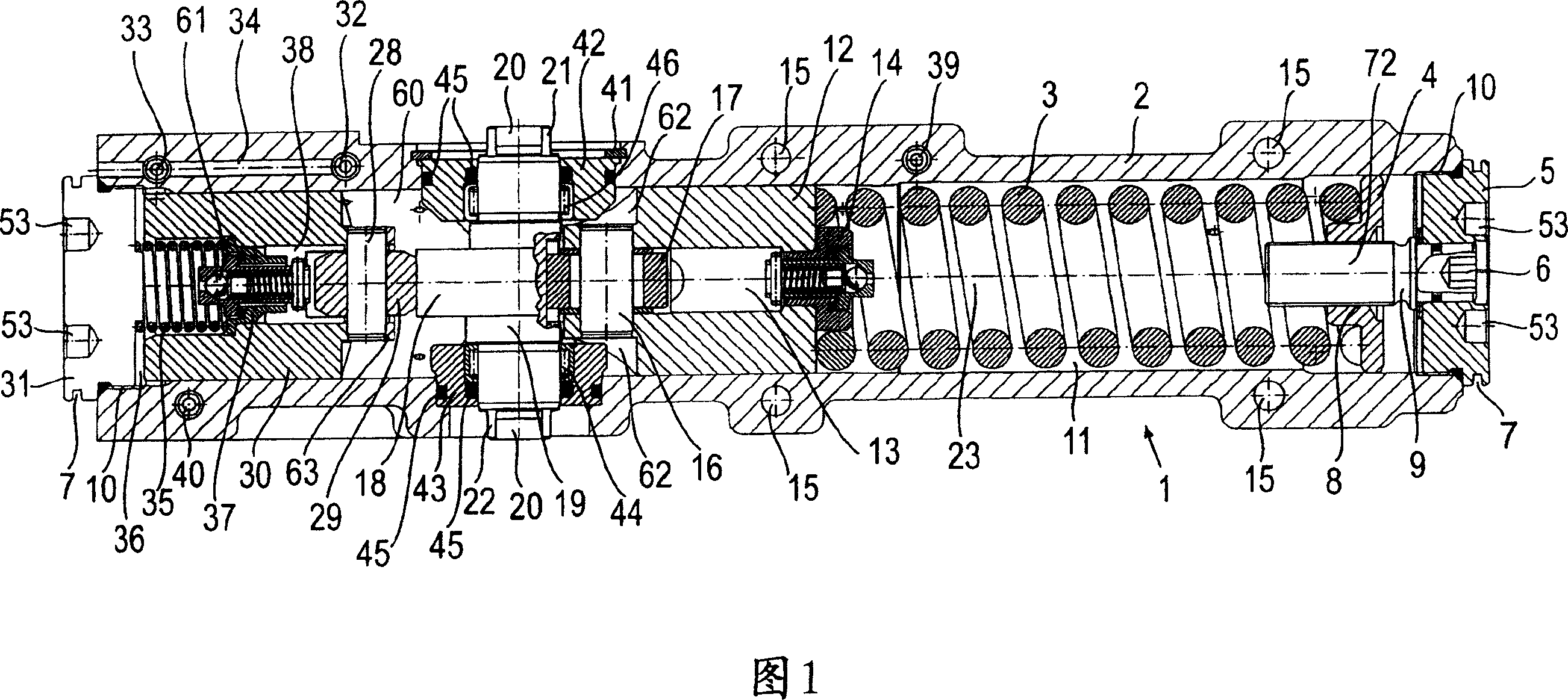
[0029] FIG. 1 shows a door closer 1 according to the invention in a sectional view, wherein the housing 2 is sectioned in the axial direction of the front view. Housing 2 has a continuous cylindrical chamber which is divided into different regions such as spring chamber 11 , crankshaft chamber 60 and pressure equalization chamber 36 . The spring chamber 11 is substantially occupied by a compression spring, wherein the compression spring 11 bears on the left side on an opening piston 12 and on its right side on a spring bearing disc 4, which is a component of a spring force adjustment device 9 . The spring force adjusting device basically comprises a journal 72 which has an external thread and is screwed into the spring support disk 4 . In order to be able to adjust the spring force, the spring force adjustment device 9 protrudes outside the housing 2 . For this purpose, the spring force adjustment device 9 projects into the locking screw 5 . For adjustment, a recess 6 for t...


PUM


Abstract

The door closer includes one rectangular casing, which has closing screws and end caps on two sides and one protecting board between two end caps, and is separated into one spring cavity, one crankshaft cavity and one pressure balancing cavity; one opening piston and one compression spring connected together inside the spring cavity; and one driving device inside the crankshaft cavity and including one driving shaft, one cam disc connected to the driving shaft, one operating arm with one end connected to the driving shaft and one sliding block connected to the other end of the operating arm and capable of shifting inside one slide rail.

Description

technical field [0001] The present invention relates to a door closer comprising a single-piece elongated housing having a locking screw at each end, said locking screw being provided with an end cover external to the housing. surrounding grooves. A through cylindrical hole is provided in the housing, in which on one side an opening piston is in operative connection with a pressure spring and on the other side of the door opening piston is connected to a transmission driving device, said driving device It is also effectively connected with a buffer piston. For this purpose, the geared device has a drive shaft with two outputs outside the housing. Background technique [0002] Such a door closer has proven to be suitable in practice due to its reliability and various application possibilities. Such a door closer can be mounted not only on the inside of a door leaf but also on the outside of the door leaf as well as on the door frame or the like. [0003] A known upper doo...

Claims


Application Information

Patent Timeline
Patent Type & Authority Applications(China)
IPC IPC(8): E05F3/00E05F3/12E05F1/12
Inventor B·内勒斯
Owner DORMAKABA DEUT GMBH
Why Eureka
Try Eureka