

Fridge with movable middle beam Split door
A technology of movable middle beams and side-opening doors, which is applied to home appliances, household refrigeration devices, lighting and heating equipment, etc., and can solve the problems affecting the sealing effect of movable middle beams and door bodies, and easy deviations in the docking of guide shafts and guide grooves, etc. problem, achieve the effect of maintaining the ambient temperature and preventing the leakage of cold air
- Summary
- Abstract
- Description
- Claims
- Application Information
AI Technical Summary
Problems solved by technology
Method used
Image

Examples
Embodiment 1
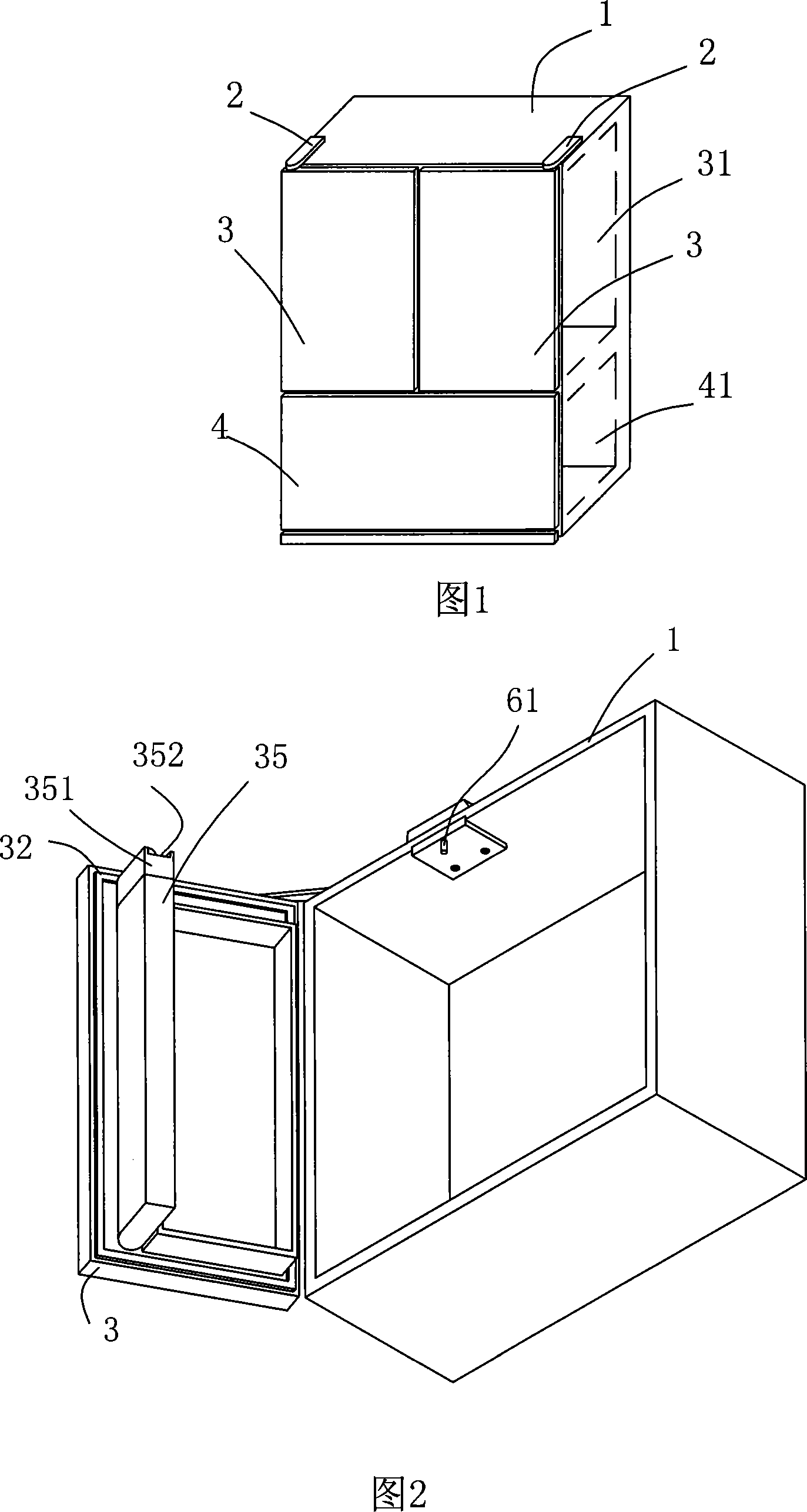
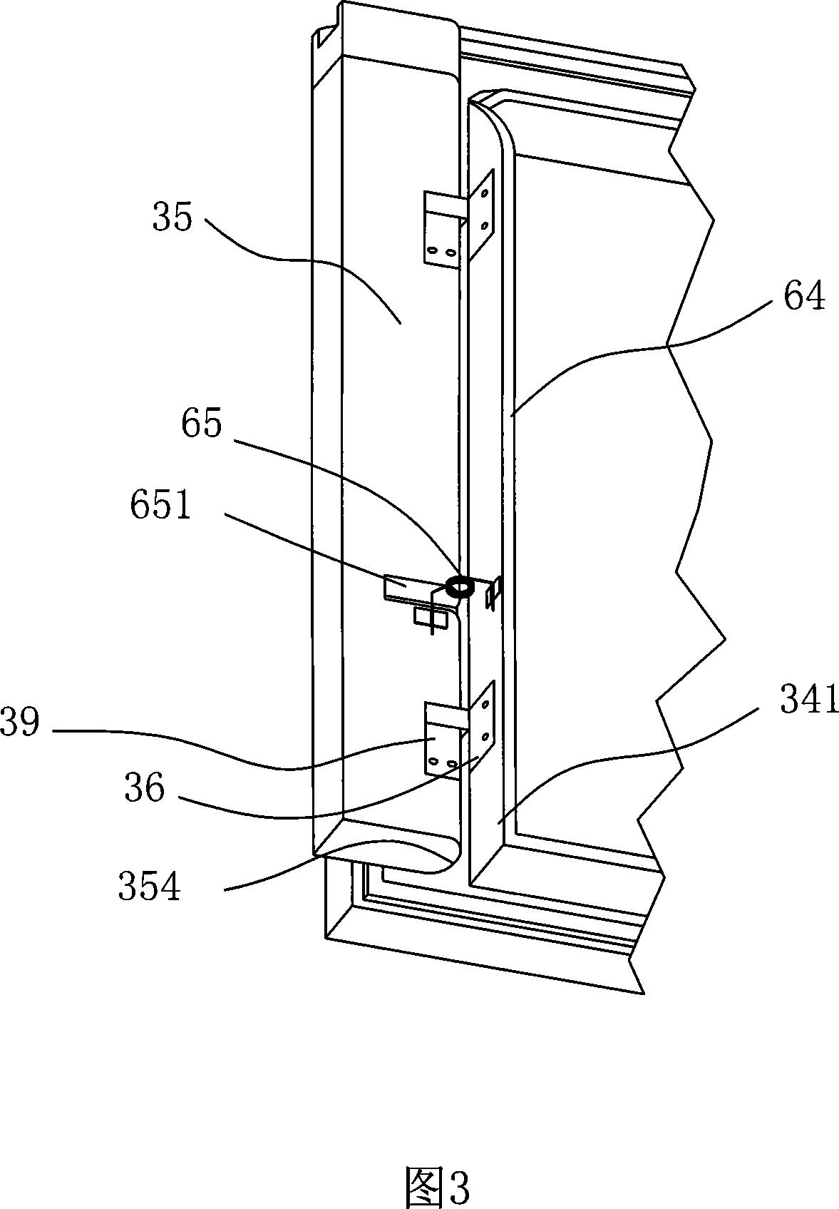
[0075] Embodiment 1, wherein, as shown in Figure 2, a ring of sealing strip 32 is arranged on the inner side of the left door body 3, and a movable middle beam 35 is arranged on the inner side of the sealing strip 32, and one side of the movable middle beam 35 passes through a hinge 36 Connect with the side wall 341;
[0076] The movable middle beam 35 is used for the refrigerator with side-by-side doors, and there is no intermediate partition inside the refrigerated compartment 31, and the gap between the door bodies 3 on both sides is blocked by the movable central beam 35 to prevent the refrigerated compartment 31 from The air-conditioning is gone.
[0077] The movable middle beam 35 is a strip structure with a rectangular cross section, which is installed on the inside of any one of the door bodies 3 on both sides, while the other side door body is not provided with a movable middle beam 35 (not shown in the figure). the side door body shown).
[0078] As shown in FIG. 2...
Embodiment 2
[0098] Embodiment 2, as shown in Figures 13, 15 and 16, a ring of sealing strip 32 is arranged on the inner side of the right-hand side-by-side door body 3, a lining 33 is arranged inside the sealing strip 32, and a storage tank is arranged on the lining 33. Object box 34.
[0099] A columnar movable middle beam 35 is arranged inside the inner lining 33 , and one side of the movable middle beam 35 is connected with the inner lining 33 through a hinge 36 . A buffer pad 38 is arranged between the movable beam 35 and the inner lining 33 to reduce the impact on the inner lining 33 when the movable beam 35 rotates.
[0100] As shown in Figures 13 to 20, at least one end of the top and bottom of the beam 35 is provided with a protruding slider 37, and a positioning block 13 is respectively provided at the top and bottom of the inner side of the refrigerated compartment 31. A concave chute 12. Specifically, the chute 12 has a horizontally arranged rectangular butt joint section for...
Embodiment 3
[0108] Embodiment 3, referring to FIG. 15 and comparing the content of the above-mentioned embodiment 2, is different from embodiment 2 in that a fixing bracket 40 is arranged inside the door body 3 , and a magnetic strip 42 is arranged inside the fixing bracket 40 .
[0109] Correspondingly, the magnetic strip 401 of the active beam is not arranged on its back, but on its side. When the door body 3 is opened by the user, the movable middle beam 35 rotates to the inside of the fixed bracket 40, and the movable middle beam 35 is limited and fixed on the inner side of the bracket 40 through the magnetic attraction between the above-mentioned magnetic strips, which is beneficial to The movable center beam 35 is positioned smoothly.
[0110] The cross-sectional shape of the fixing bracket 40 is "L", and is formed integrally with the door liner 33 by blistering.
[0111] The other structural features of Embodiment 3 are basically the same as those of Embodiment 2, and will not be ...
PUM
 Abstract
Description
Claims
Application Information