Method for making micro-magnetic field integrated polyalcohol microflow control device
A technology of microfluidic devices and manufacturing methods, applied in the field of micro-total analysis systems, can solve problems such as high cost, low integration, and complicated processing, and achieve simple processing and manufacturing processes and methods, in-situ integration, and direction controllable effect
- Summary
- Abstract
- Description
- Claims
- Application Information
AI Technical Summary
Problems solved by technology
Method used
Image
Examples
Embodiment 1
[0026] (1) Prepare the silicon positive mold template for the polydimethylsiloxane microfluidic chip by soft etching;
[0027] (2) winding 40 turns of enamelled copper wire on an iron core with a diameter of 1mm to make a microcoil (4), wherein the diameter of the enamelled copper wire is 0.1mm;
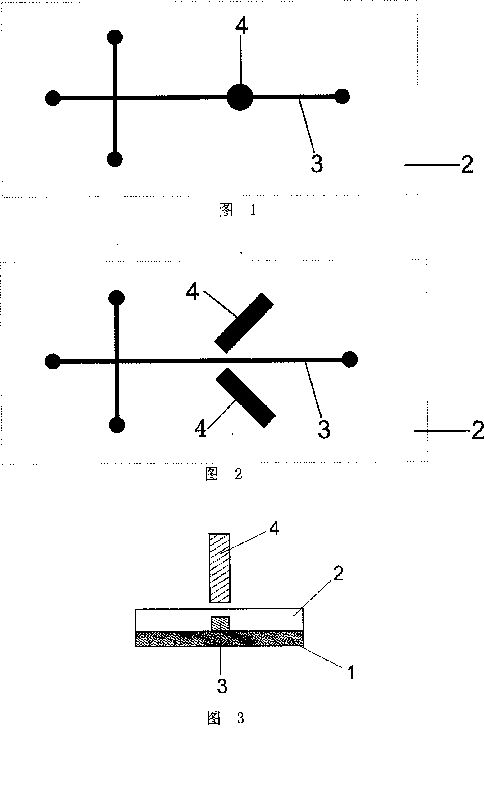
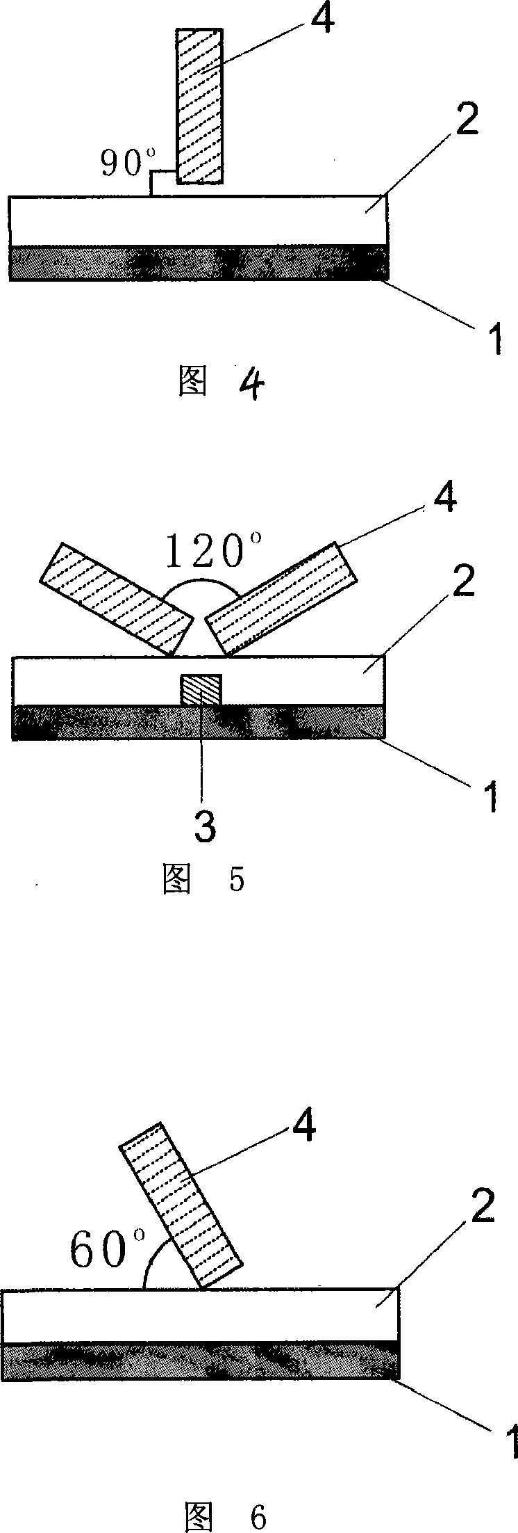
[0028] (3) Two 40-turn microcoils (4) are fixed on both sides of the microchannel on the silicon positive mold template, the angle between the coils is 120°, and the plane formed by the two coils and the plane of the template are clamped. The angle is 60°;
[0029] (4) Mix the polydimethylsiloxane monomer and the curing agent in a ratio of 10:1, stir thoroughly, remove air bubbles and pour it on the silicon positive mold template for fixing the microcoil, and cure at 80°C for 3 hours, Then the cured polydimethylsiloxane is peeled off from the silicon positive mold template to make a chip substrate with microcoils (4) and microchannels (3);
[0030] (5) Punch holes on the chip subst...
Embodiment 2
[0032] (1) A positive glass mold template for the polydimethylsiloxane microfluidic chip is prepared by soft etching;
[0033] (2) Winding 60 turns of enamelled copper wire on an iron core with a diameter of 1.2mm to make a microcoil; wherein the diameter of the enamelled copper wire is 0.1mm;
[0034] (3) Two 60-turn microcoils are fixed on both sides of the microchannel of the glass male template, the angle between the coils is 120°, the plane formed by the two coils and the plane of the glass male template the angle is 90°;
[0035] (4) Mix the polydimethylsiloxane monomer and the curing agent in a ratio of 10:1, stir well, remove air bubbles, pour it on the glass positive mold template for fixing the microcoil, and cure it at 80°C for 3 hours, The cured polydimethylsiloxane is then peeled off from the positive glass template to make a chip substrate with microcoils and microchannels;
[0036] (5) Punch holes on the chip substrate with a puncher, and then use plasma oxida...
Embodiment 3
[0038] (1) Prepare the silicon positive mold template for the polydimethylsiloxane microfluidic chip by soft etching;
[0039] (2) Winding 60 turns of enamelled copper wire on an iron core with a diameter of 1.5mm to make a microcoil, wherein the diameter of the enamelled copper wire is 0.1mm;
[0040] (3) Two 60-turn microcoils are fixed on both sides of the microchannel of the silicon positive mold template, the angle between the coils is 60 °, the plane formed by the two coils and the plane of the silicon positive mold template The included angle is 90°;
[0041] (4) Mix the polydimethylsiloxane monomer and the curing agent in a ratio of 10:1, stir well, remove air bubbles and pour it on the chip silicon positive mold template for fixing the microcoil, and cure at 80°C for 3 hours , and then peel off the cured polydimethylsiloxane from the silicon positive mold template to make a chip substrate with microcoils and microchannels;
[0042] (5) Punch holes on the chip substr...
PUM
| Property | Measurement | Unit |
|---|---|---|
| Diameter | aaaaa | aaaaa |
| Diameter | aaaaa | aaaaa |
Abstract
Description
Claims
Application Information
 - R&D Engineer
- R&D Manager
- IP Professional
- Industry Leading Data Capabilities
- Powerful AI technology
- Patent DNA Extraction
Browse by: Latest US Patents, China's latest patents, Technical Efficacy Thesaurus, Application Domain, Technology Topic.
© 2024 PatSnap. All rights reserved.Legal|Privacy policy|Modern Slavery Act Transparency Statement|Sitemap


