Aneurysm clamp holding forceps

An aneurysm clip and clamping plate technology, applied in the field of medical devices, can solve the problems such as the inability to rotate the head, the instability of the holder, and the inflexibility, so as to be beneficial to popularization and promotion, reduce production costs, and avoid restricted vision. Effect

Active Publication Date: 2020-04-10
LISHUI PEOPLES HOSPITAL
View PDF4 Cites 1 Cited by
  • Summary
  • Abstract
  • Description
  • Claims
  • Application Information

AI Technical Summary

Problems solved by technology

The gun-shaped finger-ring placement forceps CASPAR clip holding forceps can be rotated freely within 360° to ensure smooth placement of cerebral aneurysms at any angle. Due to the limitation, it is easy to cause the holder to be unstable
The operation requires precise positioning, so the operation is more difficult, and the surgical field of view is limited. The tweezers-type placement forceps, such as the YASARCIL clip holding forceps, are five-finger holders, which solve the above-mentioned problems that the CASPAR clip holding forceps has two fingers. However, because the jaws are scissor-shaped, the jaws are limited by their structure and cannot be rotated. Therefore, it is not convenient to place cerebral aneurysms smoothly in different diseased parts. The first generation of aneurysm clips often block the surgical line of sight. Improvement The latter is a direction-adjustable aneurysm clamp holding forceps combined with the principle of a serpentine pull hook. The middle section of the rod can be made into an aneurysm holding forceps that can be freely transformed into any angle, which is convenient for handling aneurysms of different angles during surgery.
The second-generation head is made smaller, but it is still not flexible enough, and the angle of the head cannot be rotated, so it is necessary to design a new type of aneurysm clip holding forceps to solve these problems

Method used


Image

  • Aneurysm clamp holding forceps
  • Aneurysm clamp holding forceps
  • Aneurysm clamp holding forceps

Examples


Embodiment Construction

[0025] In order to make the technical means, creative features, goals and effects achieved by the present invention easy to understand, the present invention will be further described below in conjunction with specific embodiments.

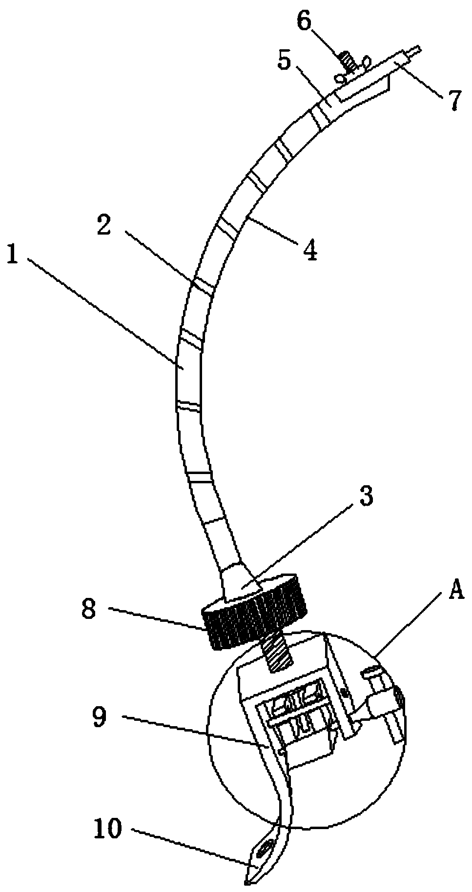
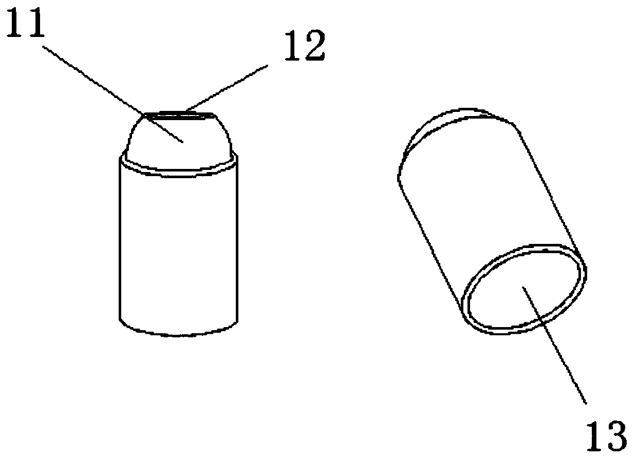
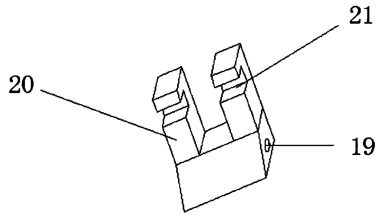
[0026] Such as Figure 1-5 As shown, an aneurysm clip holding forceps includes a clip holding forceps main body 1, a serpentine arm 2 is fixedly arranged on the clip holding forceps main body 1, and the serpentine arm 2 is composed of a bottom joint 3 and several intermediate joints 4 and a top joint 5 are spliced ​​together, and the top of the bottom joint 3 and the top of the middle joint 4 are fixedly provided with ball knots 11, and the bottoms of the middle joint 4 and the top joint 5 are fixedly provided with ball knots for placement Groove 13, the top joint 5 is threadedly connected with the pincer head 7 through the double ear nut 6, and the lower part of the bottom joint 3 is fixedly provided with a clamping force adjustment knob 8, and t...


PUM


Abstract

The invention discloses a pair of aneurysm clamp holding forceps, which comprises a clamp holding forceps body, according to the invention, the snake-shaped arms are arranged on the clamp holding forceps main body; the snake-shaped arm is formed by splicing a bottom joint, a plurality of middle joints and a top joint; ball knots are fixedly arranged at the top of the bottom joint and the top of the middle joint; the bottoms of the middle joint and the top joint are both fixedly provided with ball joint containing grooves, the snake-shaped arm can be adjusted to any angle flexibly and conveniently, meanwhile, the angle of a forceps head can be adjusted through a double-lug nut, and the defects that an existing clamp holding forceps head is not flexible enough and cannot rotate are overcome.The bottom joint, the middle joint and the top joint are all internal hollow pipes, so that the overall weight is reduced, and meanwhile, the manufacturing cost is reduced. By arranging the operatingmechanism below the bottom joint, the forceps head can be operated at the far end, the view limitation in the operation process can be effectively avoided, and popularization and promotion are facilitated.

Description

technical field [0001] The invention relates to the technical field of medical instruments, in particular to an aneurysm clip holding forceps. Background technique [0002] Intracranial aneurysm refers to a tumor-like protrusion of the arterial wall caused by a localized abnormal expansion of the lumen of a cerebral artery. Intracranial aneurysm is mostly caused by cystic bulge due to local congenital defects of the cerebral artery wall and increased intracavitary pressure. It is the first cause of subarachnoid hemorrhage. The cause of aneurysm is not very clear. The etiology of neoplasia can be summarized as follows: ①Congenital factors; ②Atherosclerosis; ③Infection; ④Trauma. In addition, there are some rare reasons such as tumors can also cause aneurysms, abnormal skull base vascular network disease, cerebral arteriovenous malformation, intracranial vascular abnormalities and cerebral artery occlusion can also be associated with aneurysms. [0003] At present, there are ...

Claims


Application Information

Patent Timeline
Patent Type & Authority Applications(China)
IPC IPC(8): A61B17/29
CPCA61B17/2909A61B2017/2927A61B2017/2932
Inventor 刘进吴凌慧苏畅李衍文张培军王伟明
Owner LISHUI PEOPLES HOSPITAL
Why Eureka
Try Eureka