Stepped labyrinth seal decompressing ring for filling compressor

A technology of labyrinth seals and decompression rings, which is applied to engine seals, mechanical equipment, engine components, etc., can solve the problems of short service life of packing and insufficient protection of high-pressure packing sealing rings, etc. , to reduce the effect of impact

Inactive Publication Date: 2008-03-12
WUXI COMPRESSOR CO LTD
View PDF0 Cites 3 Cited by
  • Summary
  • Abstract
  • Description
  • Claims
  • Application Information

AI Technical Summary

Problems solved by technology

[0007] The traditional decompression ring adopts the method of small hole throttling, which can only reduce 30% of the pulse pressure for the sealing ring, which is insufficient for the protection of the high-pressure packing sealing ring, so that the service life of the packing is shortened

Method used


Image

  • Stepped labyrinth seal decompressing ring for filling compressor

Examples


Embodiment Construction

[0014] Below the present invention will be further described in conjunction with the embodiment in the accompanying drawing:

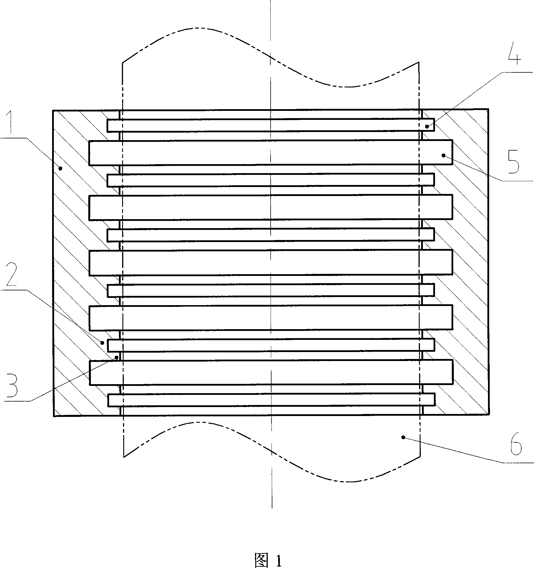
[0015] The present invention is mainly composed of decompression ring 1, high teeth 2, low teeth 3, auxiliary sealing chamber 4 and main sealing chamber 5.

[0016] As shown in Fig. 1 : a plurality of high teeth 2 are arranged on the inner ring of the decompression ring 1, and a main sealing chamber 5 is formed between two adjacent high teeth 2, and the main sealing chamber 5 adopts a labyrinth sealing structure. Two low teeth 3 are arranged on the high teeth 2 , and a secondary sealed chamber 4 is formed between the two low teeth 3 . The secondary sealing chamber 4 adopts a labyrinth sealing structure. The high-pressure gas passes through the gap between the lower teeth 3 of the inner ring of the decompression ring 1 and the surface of the piston rod 6, and then flows from the high-pressure side of the decompression ring 1 to the low pressure side. ...


PUM


Abstract

The invention relates to a sealing decompression ring arranged in a high and low teeth labyrinth for compressor fillers, in specific to filler sealings between compression chambers and piston rods of compressor air cylinders. The invention belongs to the field of sealing technologies and mainly adopts a plurality of high teeth on the interior loop of decompression rings, so as to form a main sealing chamber between every two adjacent high teeth. Each high tooth is composed of two low teeth, and between the two low teeth, a secondary sealing chamber is formed. The invention is characterized by simple, compact and reasonable structure; because of the labyrinth sealing structure with high and low teeth on the interior loop of the decompression rings, it is possible to lower impulse pressure of the air cylinder compression chambers to filler O-rings, and meanwhile, to reduce contact area between the decompression rings and the piston rods, and to decrease friction heat; Moreover, flow restriction effects are so considerable as to lower impulse pressure by 70 percent, prolong service life of filler O-rings, and lower the cost in compressor manufacturing, utilization and maintenance.

Description

technical field [0001] The invention relates to a high-low-tooth labyrinth seal decompression ring for compressor packing, in particular to a packing seal between a compressor cylinder compression cavity and a piston rod, and belongs to the sealing technical field. Background technique [0002] With the rapid increase of domestic vehicles using natural gas as fuel, CNG (COMPRESSEDNATURAL GAS) filling stations are also growing rapidly at the same time. As the core equipment of the gas filling station, the CNG compressor's working stability is particularly important for the normal operation of the gas filling station. [0003] In order to fill up a car using CNG, the final exhaust pressure of the CNG compressor is generally as high as 25MPa. Due to the different structures of various CNG compressors, the final stage of some CNG compressors is on the shaft side close to the fuselage, that is, the pressure sealed by the packing between the compression chamber of the compressor ...

Claims


Application Information

Patent Timeline
Patent Type & Authority Applications(China)
IPC IPC(8): F04B39/00F16J15/16
Inventor 陆龙胜周耘朱为宇吴文莉华勇藤士龙
Owner WUXI COMPRESSOR CO LTD
Why Eureka
Try Eureka