Liquid, electric rectilinear movement executor

A linear motion, actuator technology, applied in fluid pressure actuation devices, non-electric variable control, instruments, etc., can solve the problems of high positioning accuracy, difficult to achieve driving power, etc., and achieve the effect of fast output power

Inactive Publication Date: 2008-03-12
杜彦亭
View PDF0 Cites 14 Cited by
  • Summary
  • Abstract
  • Description
  • Claims
  • Application Information

AI Technical Summary

Problems solved by technology

However, it is not easy to meet the requirements of high comprehensive performance such as high driving power, high positioning accuracy, small impact, convenient control, simple structure, and easy realization.

Method used


Image

  • Liquid, electric rectilinear movement executor

Examples


Embodiment Construction

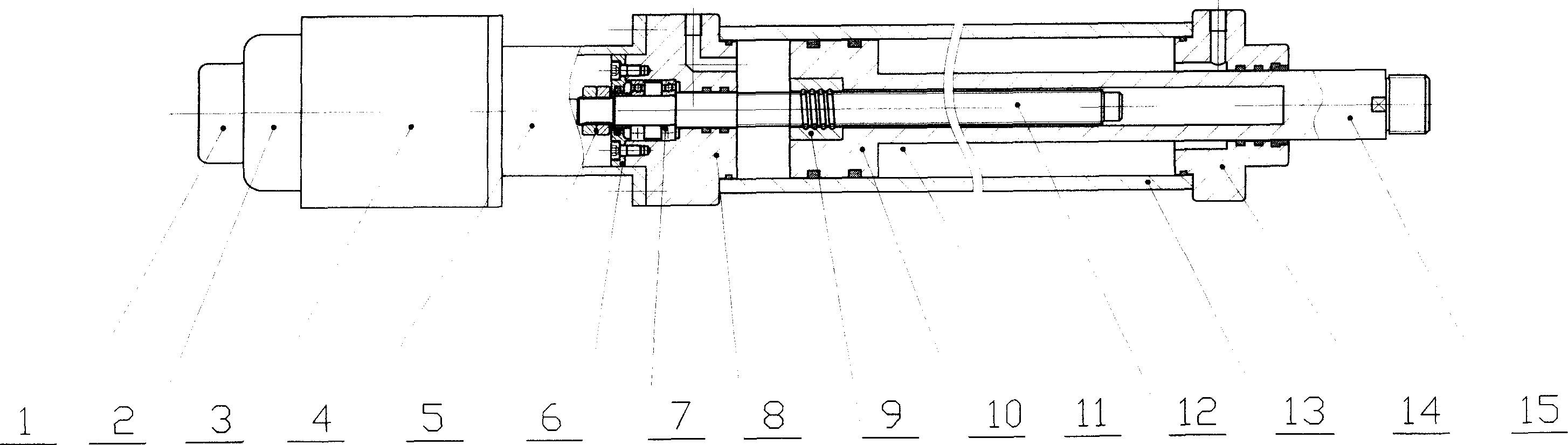
[0018] The present invention fixes the deceleration device 4, the motor 3, the electromagnetic brake 2, and the photoelectric sensor 1 on the rear end 8 of the fluid transmission cylinder, and installs a screw 12 in the rear end cover of the cylinder. The screw 12 is composed of a nut 5 and a bearing 7, and the end The cover 6 is axially fixed and can only rotate but cannot move axially. The motor 3 is connected with the lead screw 12 through the reduction device 4. The nut 9 matched with the lead screw is embedded in the piston 10. When the motor 3 is working, the lead screw 12 rotates. , the nut drives the piston to move, the lead screw is hidden in the hollow piston rod 15, and the piston and piston rod are installed in the cylinder block composed of the end caps 8, 12 and the cylinder barrel. The fluid cylinder outputs thrust and speed, and can play a guiding role. The electric screw 15 and nut 9 also output thrust and control speed, and play the functions of controlling sp...


PUM


Abstract

The invention relates to a linear motion actuator combined by the fluid drive and the lead screw nut device, which comprises a fluid drive cylinder, a lead screw nut mechanism, a motor, a speed reducer, an electromagnetic brake and a photoelectric sensor. Therefore, a linear motion execution and control unit integrating the fluid, optics, machinery and electronic functions is formed, which can conveniently realize the speed and position control of the linear motion of the high comprehensive index precision.

Description

1. Technical field [0001] The invention relates to a driving device for a mechanical mechanism to realize linear motion, in particular to a fluid, mechanical, electrical and optical integrated linear motion actuator that utilizes fluid pressure energy and mechanical energy output by a motor to jointly realize linear motion. 2. Background technology [0002] When mechanical equipment is working, it is often necessary to achieve linear motion. At present, the main ways to achieve linear motion are: rack and pinion linear motion actuators, screw nut type linear motion actuators, hydraulic pneumatic linear motion actuators, crank-connecting rod type Linear motion mechanism, pendulum slider type linear motion actuator, etc. The existing linear motion actuators have their own characteristics and are widely used in various mechanical equipment. However, it is difficult to meet the requirements of high comprehensive performance such as high driving power, high positioning accuracy,...

Claims


Application Information

Patent Timeline
Patent Type & Authority Applications(China)
IPC IPC(8): F15B15/00F15B15/16F15B15/22F15B15/28G05D13/00G05D3/12
Inventor 杜彦亭陈兴江史维祥陈花玲邱鹏邱龙涛吴博齐铭汤思远董霞白文杰
Owner 杜彦亭
Why Eureka
Try Eureka