Device especially frictionclutch or arrester and method for preparing the device

A technology for friction clutches and brakes, which is applied in the field of friction clutches or brakes to manufacture such devices. It can solve problems such as adhesion and the influence of the working performance of the device during the run-in operation stage, and achieve the effect of improving the initial friction coefficient.

Inactive Publication Date: 2008-03-12
ZF +1
View PDF1 Cites 5 Cited by
  • Summary
  • Abstract
  • Description
  • Claims
  • Application Information

AI Technical Summary

Problems solved by technology

The problem that arises when coating frictional surfaces is that, since the coating can lead to adhesion of friction pairs that frictionally interact during normal use, this has a negative effect on the performance of the device during the run-in phase

Method used


Image

  • Device especially frictionclutch or arrester and method for preparing the device
  • Device especially frictionclutch or arrester and method for preparing the device

Examples


Embodiment Construction

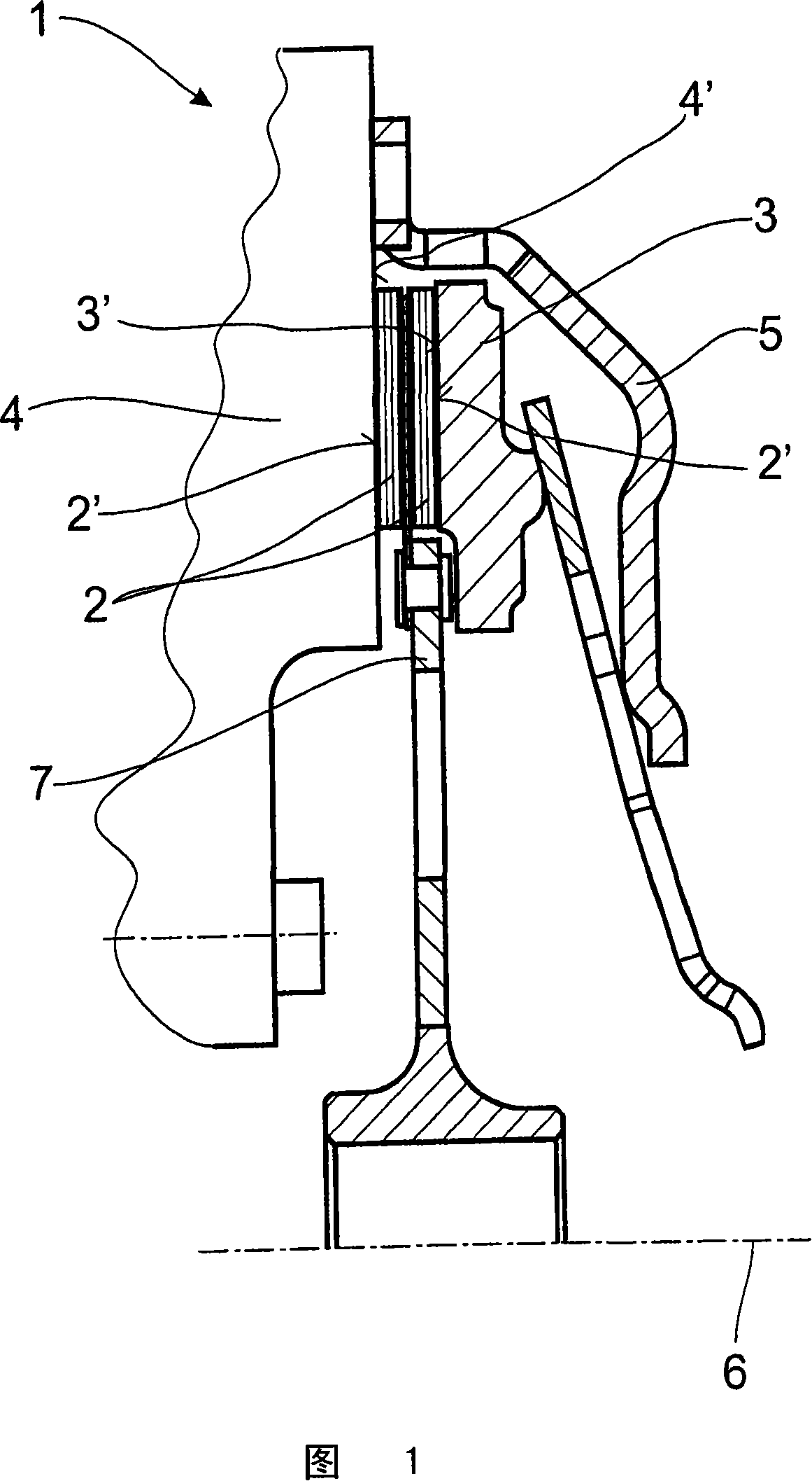
[0021] In FIG. 1 a clutch device 1 can be seen, which is constructed in a conventional manner. The clutch housing 5 is connected in a rotationally fixed manner to the flywheel 4 of the internal combustion engine, the housing 5 together with the flywheel 4 being rotatable about an axis of rotation 6 . Arranged in the housing 5 is a pressure plate 3 , which is mounted in a rotationally fixed manner relative to the housing 5 but is axially slidable. Between the pressure plate 3 and the flywheel 4 is arranged a clutch disk 7 which is provided with a friction lining 2 on each side.

[0022] If the pressure plate 3 is pressed axially in the direction of the flywheel 4, due to the frictional connection between the friction lining 2 and the flywheel 4 or between the friction lining 2 and the pressure plate 3, the torque is transferred from the flywheel 4 to a clutch disc 7 which is non-rotatably connected to a propeller shaft (not shown).

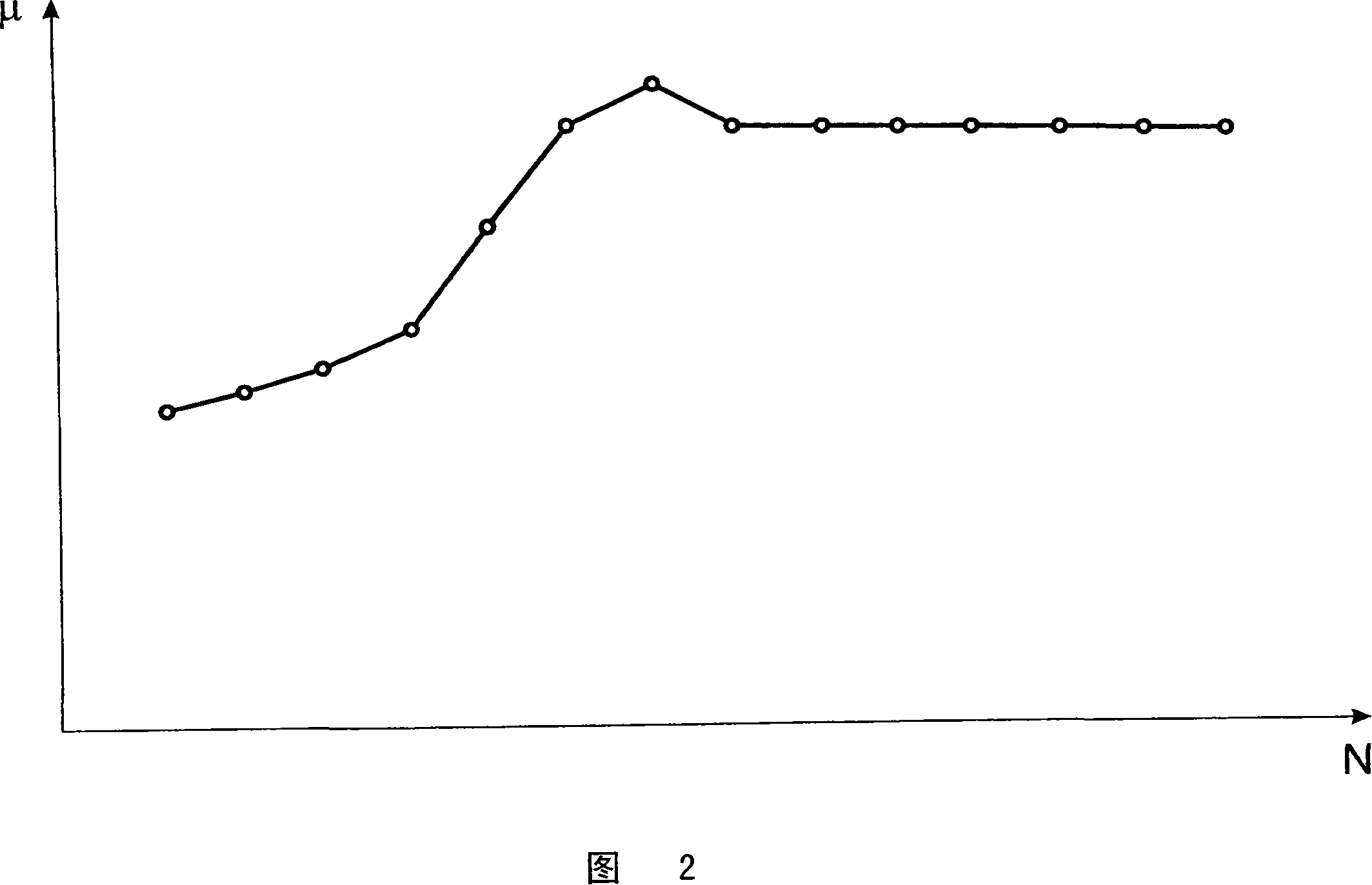
[0023] As can be seen from FIG. 2 , the co...


PUM


Abstract

The present invention relates to a device (1) especially a friction clutch or brake, wherein at least two components (2, 3 and 4) act together in routine using to transfer the torque, wherein at least one component (2, 3 and 4) is arranged with coating at the surface (2', 3' and 4') which is exposed to friction to prevent the fluctuation of the friction coefficient caused by the run-in. The invention prescribes that the coating is composed of silicone or contains silicone to get an improved run-in capability. Besides, the invention relates to a method for making the device.

Description

technical field [0001] The present invention relates to a device, and more particularly to a friction clutch or brake, in which at least two members frictionally cooperate to transmit torque in normal use, wherein at least one of the members is A coating is provided on its surface subject to friction. Furthermore, the invention relates to a method for producing such a device. Background technique [0002] It is known that the friction coefficient of the friction pair is related to the state of the friction pair. In particular, friction partners, such as in friction clutches, have varying coefficients of friction depending on the time of use or the number of load changes. FIG. 2 schematically shows the correlation between the coefficient of friction μ and the number N of load transitions in a friction clutch. In the new state of the clutch, that is to say especially with new friction linings, the coefficient of friction is still low. It increases gradually with the number...

Claims


Application Information

Patent Timeline
Patent Type & Authority Applications(China)
IPC IPC(8): F16D69/00
CPCF16D2300/10F16D69/04F16D2250/0046F16D13/58F16D13/70F16D2069/0491F16D13/64
Inventor C·威克尔
Owner ZF
Why Eureka
Try Eureka