Reversing switch
A technology for changeover switches and fixed terminals, which is applied in the direction of electric switches, electrical components, and contact engagement. It can solve the problems of not being able to improve the contact reliability of contacts, and achieve the effect of improving contact reliability.
- Summary
- Abstract
- Description
- Claims
- Application Information
AI Technical Summary
Problems solved by technology
Method used
Image

Examples
Embodiment
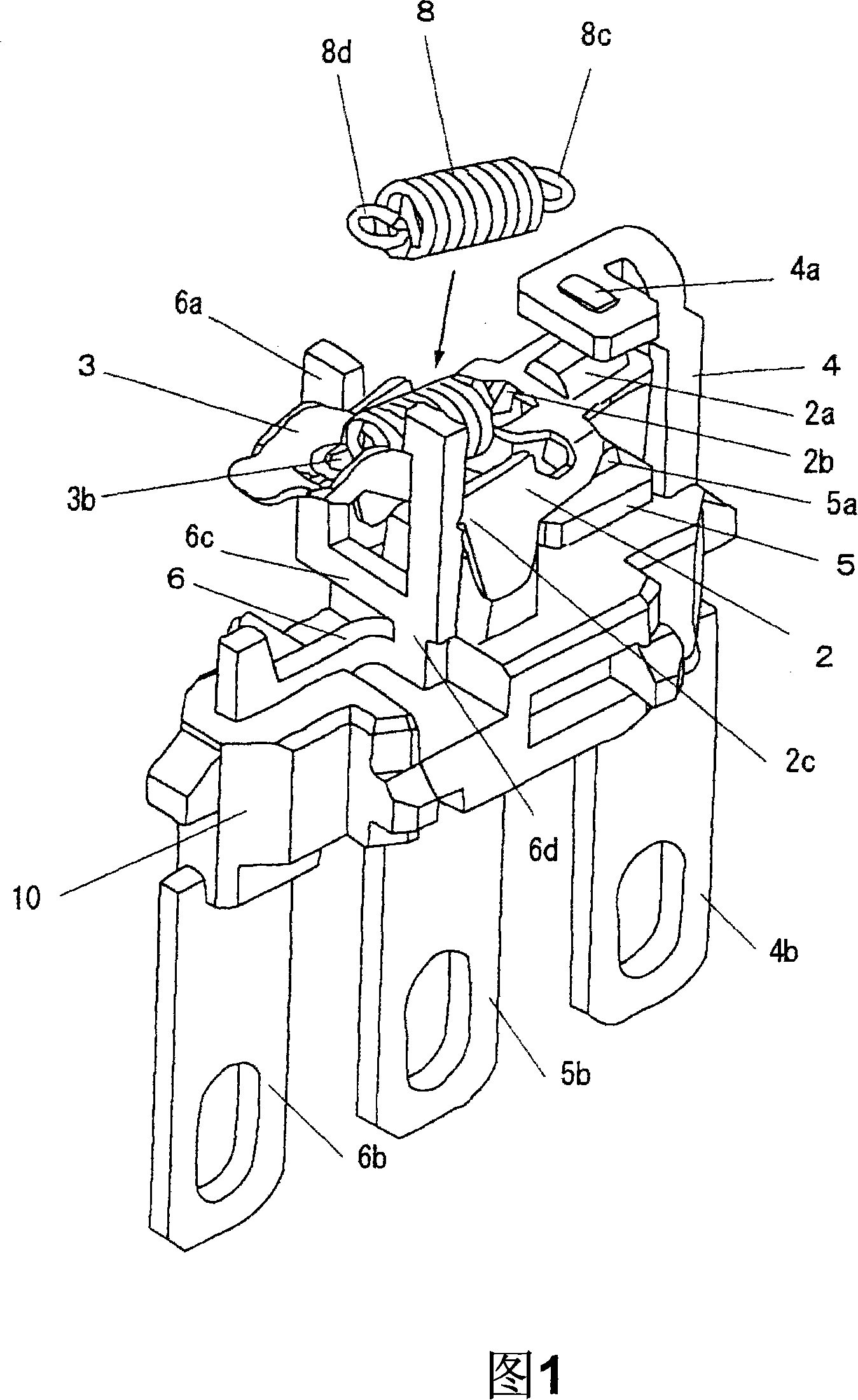
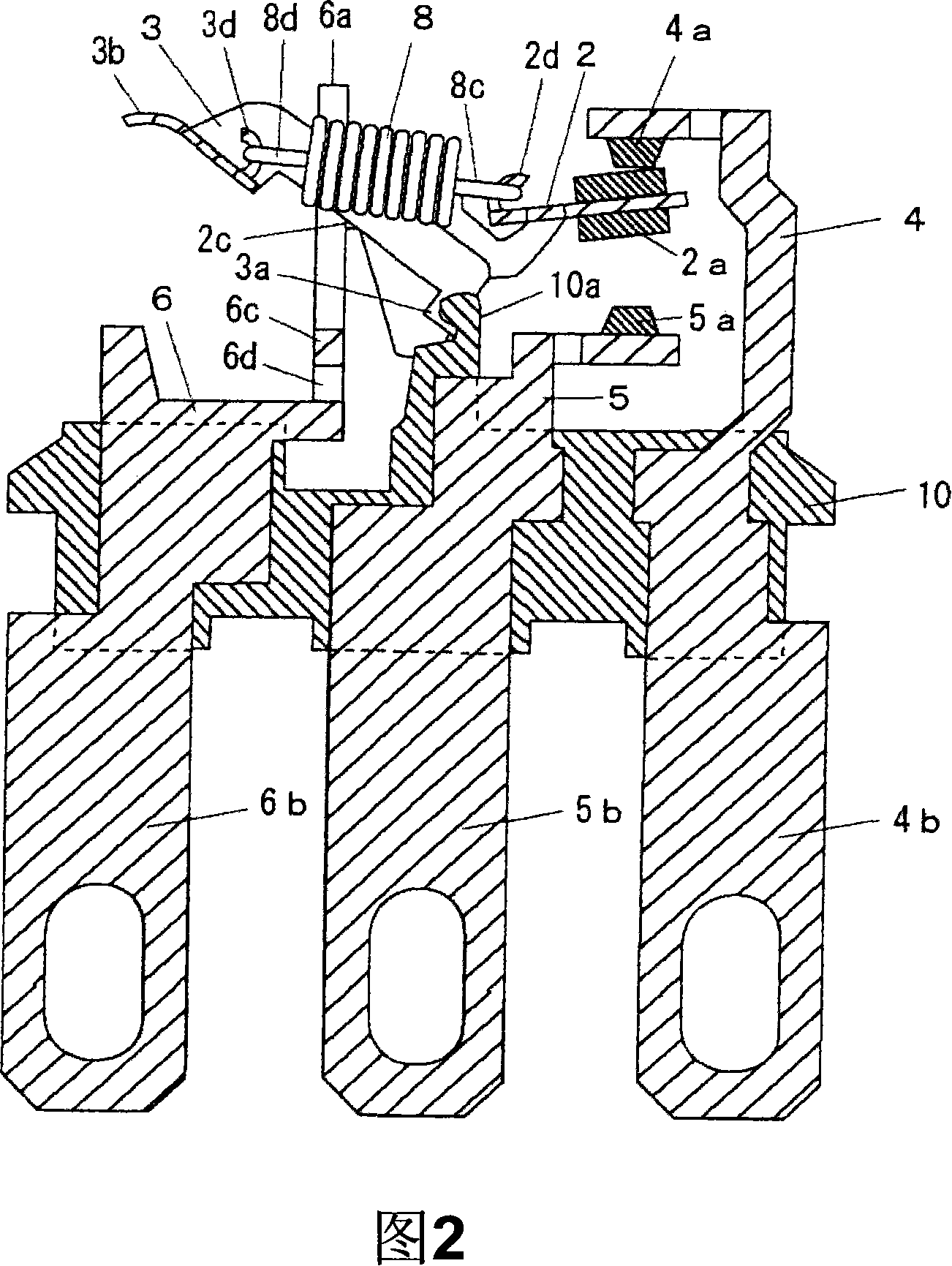
[0043] 1 and 2 are diagrams showing an embodiment of a changeover switch according to the present invention, wherein FIG. 1 is a perspective view thereof, and FIG. 2 is a longitudinal sectional view thereof.
[0044] In these figures, the same components as those of the conventional switches are denoted by the same reference numerals.
[0045] The normally closed fixed terminal board 4 and the normally open fixed terminal board 5 have a normally closed fixed contact 4a and a normally open fixed contact 5a mounted on the front end respectively, and external connection terminals 4b and 5b are integrally formed on the base end. As shown separately in FIG. 5, the common terminal plate 6 has a U-shaped support frame 6a for supporting the movable member at the front end, and an external connection terminal 6b integrally formed at the base end.
[0046] The front ends of the normally closed fixed terminal plate 4 and the normally open fixed terminal plate 5 are bent so that the norma...
PUM
 Abstract
Description
Claims
Application Information
 - Generate Ideas
- Intellectual Property
- Life Sciences
- Materials
- Tech Scout
- Unparalleled Data Quality
- Higher Quality Content
- 60% Fewer Hallucinations
Browse by: Latest US Patents, China's latest patents, Technical Efficacy Thesaurus, Application Domain, Technology Topic, Popular Technical Reports.
© 2025 PatSnap. All rights reserved.Legal|Privacy policy|Modern Slavery Act Transparency Statement|Sitemap|About US| Contact US: help@patsnap.com