Section bar

A profile, aluminum alloy profile technology, applied in the cooling/heating device of lighting device, lighting and heating equipment, electrical components, etc., can solve the problem of not being able to achieve real heat dissipation

Inactive Publication Date: 2008-03-19
DONGGUAN KINGSUN OPTOELECTRONIC CO LTD
View PDF1 Cites 6 Cited by
  • Summary
  • Abstract
  • Description
  • Claims
  • Application Information

AI Technical Summary

Problems solved by technology

However, LED illuminants also generate heat during work, which is also one of the most important reasons for restricting the promotion of LED lighting technology. In the fluorescent lamp technology disclosed in Chinese utility model patent docume

Method used


Image

  • Section bar
  • Section bar

Examples


Embodiment Construction

[0020] The present invention will be described in further detail below in conjunction with the accompanying drawings.

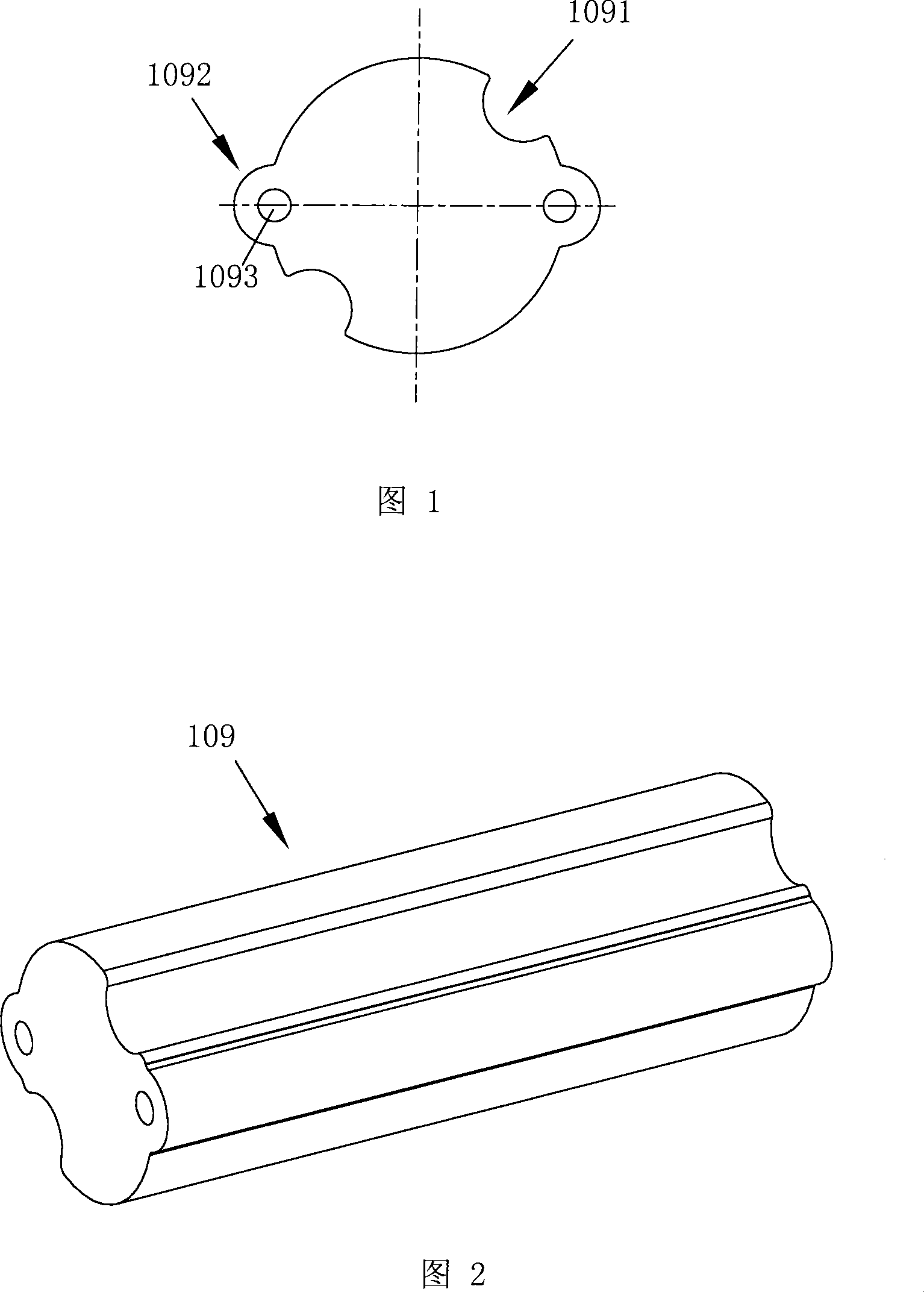
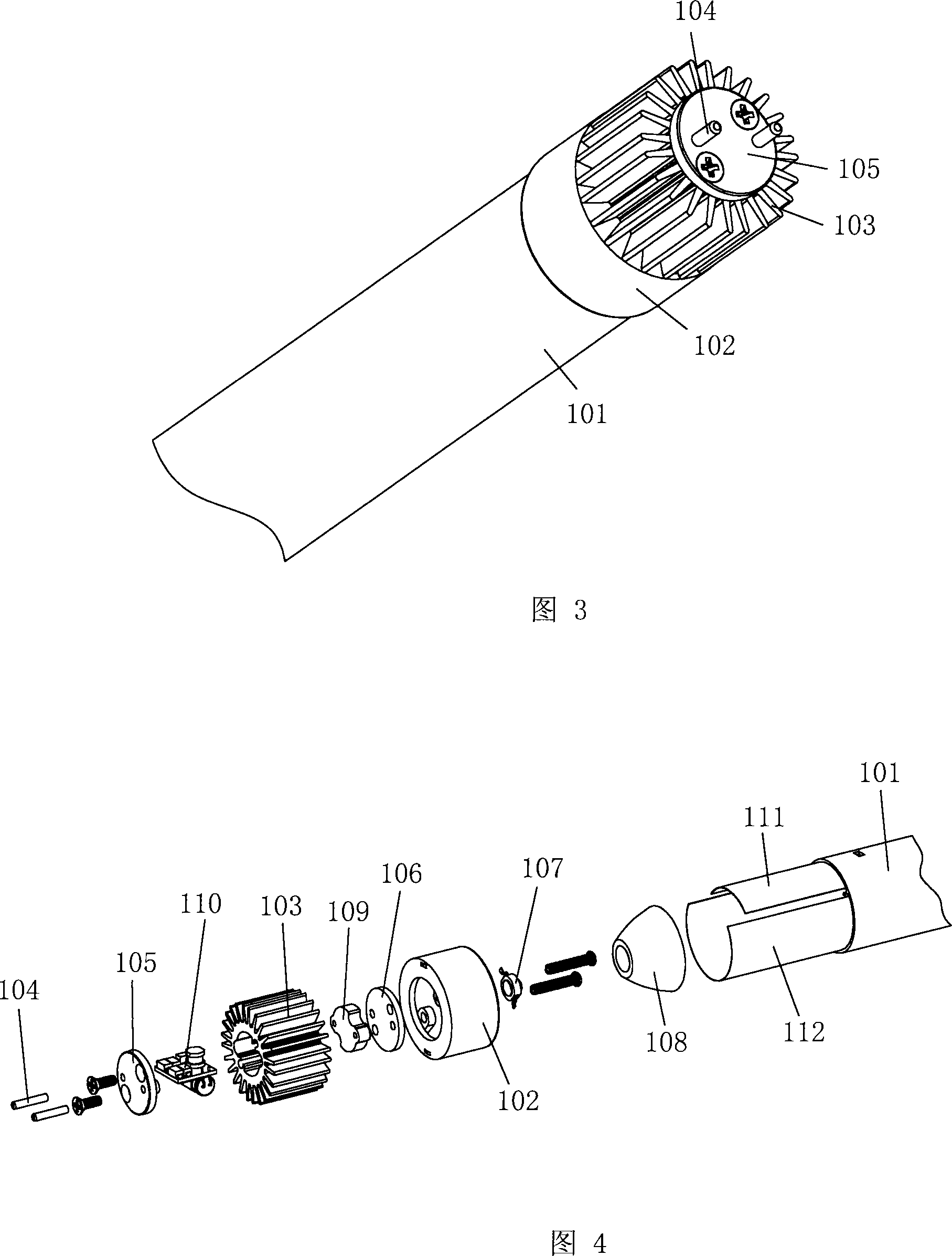
[0021] The first embodiment of the present invention is an aluminum profile. Referring to Fig. 1 and Fig. 2, along the length direction of the profile 109, different positions have the same cross-section, and the cross-section of the profile 109 consists of a circle and two Concavity 1091, two protruding positions 1092 are formed; two concavities 1091 are arranged symmetrically along a diameter of the circle, and two concavities 1091 extend along the profile length direction to form two grooves; two protruding positions 1092 are arranged symmetrically along a diameter of the circle, and two The protruding position 1092 extends along the length direction of the profile, forming two protruding ribs; the two concave positions 1091 and the two protruding positions 1092 are arranged staggered in the circumferential direction of the section; The threaded bottom hol...


PUM


Abstract

The invention relates to the LED illumination technology, in particular to a special heat radiation section material used for an LED illumination device. Different positions have the same cross section along the length direction of the section material. The invention is characterized in that the cross section of the section material consists of a circle, and two concave positions and two convex positions which are arranged on the circumference; the two concave positions are arranged symmetrically along a diameter of the circle, and extend along the length direction of the section material, in order to form two grooves; the two convex positions are arranged symmetrically along a diameter of the circle, and extend along the length direction of the section material, to form two convex ribs; the two concave positions and the two convex positions are arranged in a staggered way in the circumferential direction of the heat conducting wall; the two convex positions also have a thread bottom hole which is arranged in the length direction of the section material. The invention provides an LED daylight lamp special heat radiation section material with good heat conduction effect, and realizes the heat transmission between an LED illuminator as well as a heat radiation element outside a pipe body.

Description

technical field [0001] The invention relates to LED lighting technology, in particular to a special heat dissipation profile for LED lighting devices. Background technique [0002] Fluorescent lamps have been the mainstream of daily lighting technology for decades, and fluorescent lamps bring a lot of convenience to people's work, study and life. However, traditional fluorescent lamps generate a lot of heat while emitting light, so the light output rate is low and the life of the lamp tube is short; in addition, once the lamp tube is broken, it will pollute the environment. In recent years, LED lighting technology has developed rapidly. For example, the Chinese utility model patent document CN2926772Y discloses an LED fluorescent lamp, which includes a lamp tube and mounting heads at both ends of the lamp tube. Each LED tube is electrically connected with a power supply electric control board enclosed in the lamp tube. It installs the luminescent LED tube in the fluorescen...

Claims


Application Information

Patent Timeline
IPC IPC(8): F21V29/00F21V17/00H01L23/367H01L33/00F21Y101/02F21V29/508F21V29/77F21V29/89F21Y115/10
CPCH01L2924/0002
Inventor 李旭亮
Owner DONGGUAN KINGSUN OPTOELECTRONIC CO LTD
Why Eureka
Try Eureka