

Circuit breaker and thermal trip
A tripping device and thermal technology, applied in the field of thermal tripping devices, can solve the problems of bending of bimetals, change of tripping characteristics, etc.
- Summary
- Abstract
- Description
- Claims
- Application Information
AI Technical Summary
Problems solved by technology
Method used
Image

Examples
Embodiment approach 1
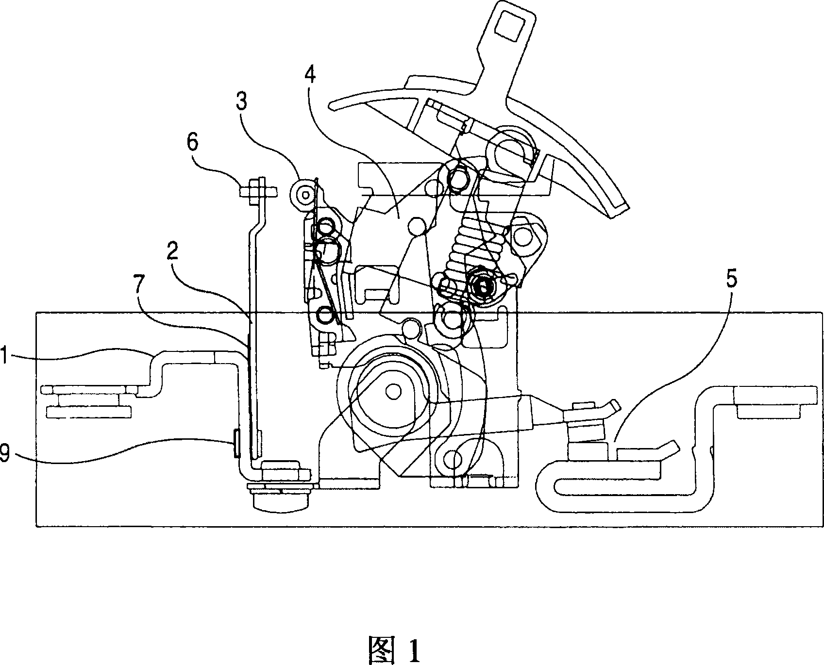
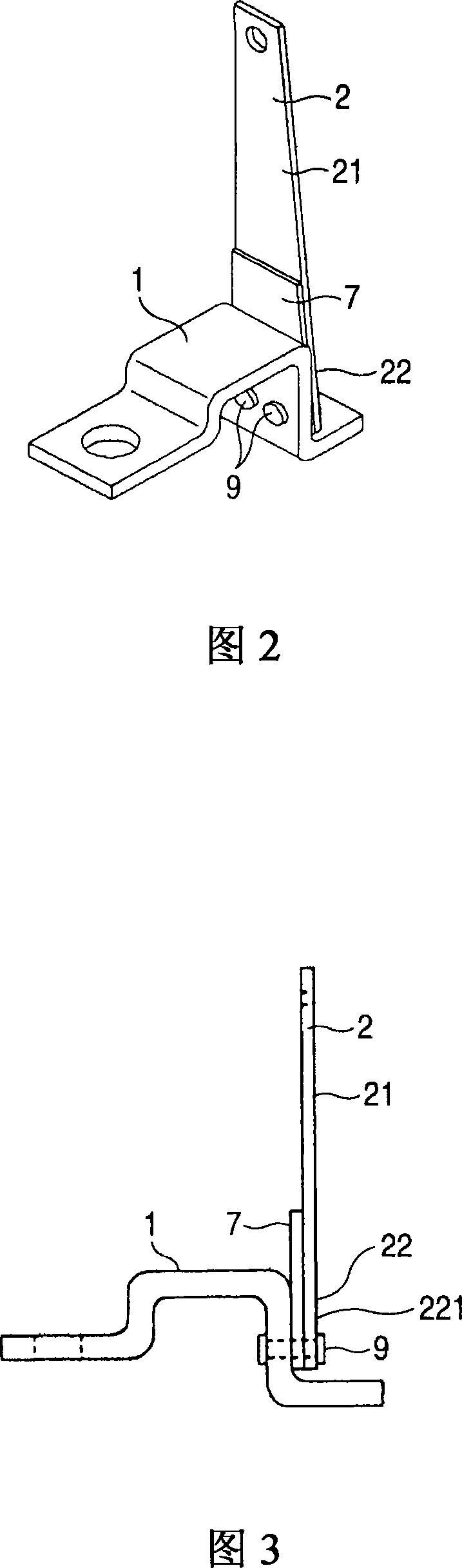
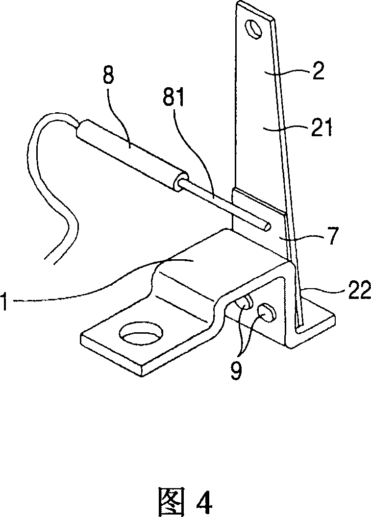
[0026] Hereinafter, Embodiment 1 of the present invention will be described with reference to FIGS. 1 to 5. Fig. 1 is a side view showing the internal mechanism of a circuit breaker having a thermal trip device, Fig. 2 is an enlarged perspective view of the thermal trip device of Fig. 1, and Fig. 3 is an enlarged view of the thermal switch of Fig. 1 A side view of a type tripping device. Fig. 4 is a perspective view for explaining the method of measuring the temperature of the bimetallic strip by a contact temperature measuring device. Fig. 5 is a perspective view for explaining the bimetallic strip when the fixed terminal (ie, the heater) is energized. An enlarged side view of the bending action. In addition, in FIGS. 1 to 5, the same parts are denoted by the same reference numerals.
[0027] In FIG. 1, the operation when an overcurrent greater than or equal to the rated current flows through the circuit breaker is as follows.
[0028] (1) The temperature of the heater 1 or the b...
Embodiment approach 2
[0047] Hereinafter, Embodiment 2 of the present invention will be described with reference to FIGS. 6 to 8. Fig. 6 is a perspective view showing the thermal trip device, Fig. 7 is a side view of the thermal trip device, and Fig. 8 is an enlarged side view for explaining the bending action of the bimetallic strip when the fixed terminal (ie, the heater) is energized .
[0048] The second embodiment of the present invention, as shown in FIGS. 6 to 8, is a case where the temperature measuring member 7 extends from the fixed end 221 of the bimetal 2 to the side opposite to the operating end 21 of the bimetal 2 example of.
[0049] In this case, the temperature measuring member 7 is formed by extending the bimetal 2 itself to the side opposite to the operating end 21. In other words, the temperature measuring member 7 is in a state exposed from the bimetal 2 and the fixed terminal (that is, the heater) 1 and is integrally fastened with the bimetal 2 to the fixed terminal (that is, the ...
Embodiment approach 3
[0053] In the third embodiment of the present invention, as shown in FIG. 9, the fixed terminal 1 is provided with a measuring element larger than the measuring element 81 of the contact type temperature measuring device 8 and inserted into the through hole 12a, and the measuring element is inserted into the through hole 12a. The measuring piece 81 is inserted into the through hole 12a so that it does not come into contact with the fixed terminal (ie, the heater) 1, and the tip of the measuring piece 81 abuts against the lower surface of the temperature measuring member 7 to measure the temperature. The temperature of the component 7 is indirectly measured for the temperature of the bimetallic strip 2. With this configuration, it is possible to achieve the same effect as the above-mentioned Embodiment 2 of the present invention.
[0054] In addition, in Embodiment 3 of the present invention, specifically, as shown in the figure, the above-mentioned measuring tool insertion through...
PUM
 Abstract
Description
Claims
Application Information