Engine blade film temperature sensor and preparation method thereof

An engine blade, film temperature technology, applied in the direction of thermometers, thermometers and instruments with directly sensitive electrical/magnetic components, etc., can solve the problem of interference with blade heat flow and temperature field, limited temperature measurement accuracy of sensors, and lead terminals. Additional potential difference and other issues to achieve the effect of improving the measurement temperature and measurement accuracy

Pending Publication Date: 2022-04-05
48TH RES INST OF CHINA ELECTRONICS TECH GROUP CORP
View PDF0 Cites 1 Cited by
  • Summary
  • Abstract
  • Description
  • Claims
  • Application Information

AI Technical Summary

Problems solved by technology

Welding thermocouple wires will destroy the blade surface, causing irreversible damage, while the thermocouple wire protrudes from the blade surface, disturbing the heat flow and temperature field around the blade, and there is a risk of falling off and damaging the turbine system
For this reason, the researchers proposed a thin-film thermocouple temperature sensor manufactured in situ on the engine blade, which can well solve the shortcomings of the above-mentioned traditional adhesive temperature sensor. However, the existing thin-film thermocouple temperature sensor based on the in-situ manufacture of the engine blade The sensor uses thermocouple homogeneous material or compensation wire as the lead material, which has certain applications for thermocouple materials that are easy to process into wires, but cannot be used for thermocouple materials that are not easy to process into wires. As a lead material, the material has certain application limitations, and it is easy to introduce an additional potential difference at the lead end, which limits the temperature measurement accuracy of the sensor, and the measurement temperature is lower than 1100°C

Method used


Image

  • Engine blade film temperature sensor and preparation method thereof
  • Engine blade film temperature sensor and preparation method thereof

Examples


Embodiment 1

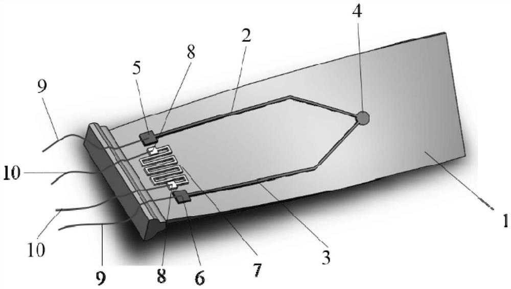
[0039] Such as figure 1 As shown, the engine blade film temperature sensor of the present embodiment includes the engine blade 1, and the engine blade 1 is provided with an insulating layer and a thermocouple film in sequence, and the thermocouple film is formed by lapping thermocouple A2 and thermocouple B3, and the overlapping Part of the thermocouple hot end 4 is used as the temperature point to be measured. The other ends of the thermocouple A2 and the thermocouple B3 are respectively provided with a pad A5 and a pad B6 to form a thermocouple cold end; between the pad A5 and the pad B6 A compensation resistance film 7 for measuring the temperature of the cold junction of the thermocouple is provided.

[0040] In this embodiment, the compensation resistor film 7 is a Pt film with a thickness of 1 μm.

[0041] In this embodiment, the two ends of the compensation resistor film 7 are also provided with pads C8, the material pads C8 of the pads C8 are on the same straight line a...


PUM

PropertyMeasurementUnit
thicknessaaaaaaaaaa
thicknessaaaaaaaaaa
thicknessaaaaaaaaaa

Abstract

The invention discloses an engine blade film temperature sensor and a preparation method thereof, the sensor comprises an engine blade, an insulating layer and a thermocouple film are sequentially arranged on the engine blade, the thermocouple film is formed by a thermocouple A and a thermocouple B in a lap joint mode, and the lap joint part forms a thermocouple hot end. The other ends of the thermocouple A and the thermocouple B are respectively provided with a bonding pad A and a bonding pad B. A compensation resistor film used for measuring the temperature of the cold end of the thermocouple is arranged between the two bonding pads. The preparation method comprises the following steps: grinding and cleaning the engine blade; and preparing an insulating layer, a thermocouple A, a thermocouple B and a compensation resistor film. The engine blade film temperature sensor has the advantages of high measurement temperature, high measurement precision, strong applicability and the like, the use value is high, the application prospect is good, the preparation method has the advantages of simple preparation process, convenience in operation, low cost and the like, and the engine blade film temperature sensor is suitable for large-scale preparation and beneficial to industrial application.

Description

technical field [0001] The invention relates to an engine blade film temperature sensor and a preparation method thereof. Background technique [0002] With the increase of the thrust-to-weight ratio of aero-engines, the rotational speed and operating temperature of the turbine blades are getting higher and higher, and blade temperature measurement is an important basic test content for blade design verification. The traditional measurement technology of engine blade temperature usually adopts the method of installing thermocouple wire, and the installation of thermocouple wire requires adhesive to connect the blade and thermocouple wire, or directly welds the thermocouple wire to the surface of the blade by welding. The selection of bonding materials, methods and processes in traditional paste-type temperature sensors has a great influence on installation performance and measurement accuracy. For example, if the thickness of the adhesive layer is too thick, it will affect ...

Claims


Application Information

Patent Timeline
Patent Type & Authority Applications(China)
IPC IPC(8): G01K7/13
Inventor 张浩车颜贤余浪周国方丁玎何峰
Owner 48TH RES INST OF CHINA ELECTRONICS TECH GROUP CORP
Why Eureka
Try Eureka