Circuit breaker and thermal trip
A tripping device, thermal technology, applied in the field of thermal tripping devices, can solve problems such as bending of bimetal strips and changes in tripping characteristics
- Summary
- Abstract
- Description
- Claims
- Application Information
AI Technical Summary
Problems solved by technology
Method used
Image
Examples
Embodiment approach 1
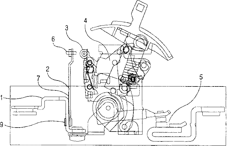
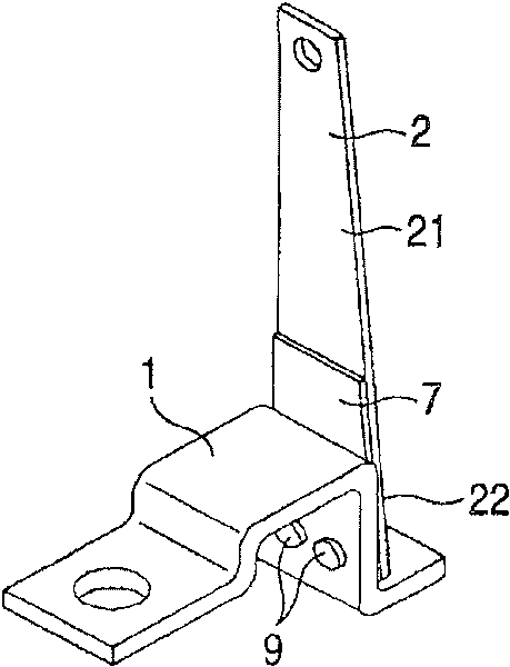
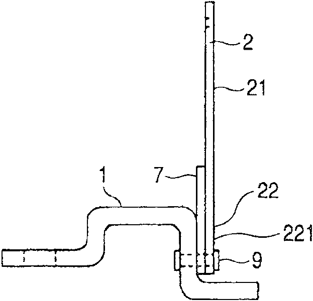
[0026] The following pass Figure 1 to Figure 5 Embodiment 1 of the present invention will be described. figure 1 It is a side view showing the internal mechanism part of the case of a circuit breaker with a thermal tripping device, figure 2 is enlarged figure 1 Oblique view of the thermal tripping device, image 3 is enlarged figure 1 Side view of the thermal trip unit, Figure 4 It is a perspective view for explaining the method of measuring the temperature of a bimetallic strip with a contact thermometer, Figure 5 It is an enlarged side view for explaining the bending action of the bimetal when the fixed terminal (that is, the heater) is energized. also, Figure 1 to Figure 5 In , the same symbols are assigned to the same parts.
[0027] exist figure 1 In , the operation when an overcurrent equal to or greater than the rated current flows through the circuit breaker is as follows.
[0028] (1) The temperature of the heater 1 or the bimetal 2 rises due to an overc...
Embodiment approach 2
[0047] Below, through Figure 6 ~ Figure 8 Embodiment 2 of the present invention will be described. Figure 6 It is an oblique view showing the thermal tripping device, Figure 7 is a side view of the thermal trip unit, Figure 8 It is an enlarged side view for explaining the bending action of the bimetal when the fixed terminal (that is, the heater) is energized.
[0048] Embodiment 2 of the present invention is as Figure 6 ~ Figure 8 Shown is an example of a case where the temperature measuring member 7 extends from the fixed end portion 221 of the bimetal strip 2 to the side opposite to the operating end portion 21 of the bimetal strip.
[0049] In this case, the temperature measuring member 7 is formed by extending the bimetal 2 itself to the side opposite to the operating end 21 . In other words, the temperature measuring member 7 is integrally fastened to the fixed terminal (ie, the heater) 1 with the above-mentioned bimetallic piece 2 in a state exposed from the ab...
Embodiment approach 3
[0053] In Embodiment 3 of the present invention, as Figure 9 As shown, a measuring piece insertion through hole 12a having a larger diameter than the measuring piece 81 of the contact temperature measuring device 8 is provided on the fixed terminal 1, and the measuring piece 81 is inserted into the measuring piece insertion through hole 12a to Make it will not be in contact with the above-mentioned fixed terminal (ie, the heater) 1, and measure the temperature of the temperature measuring member 7 by the front end of the above-mentioned measuring piece 81 abutting against the lower surface of the above-mentioned temperature measuring member 7, and measure the temperature of the bimetal 2 indirectly. temperature. With such a configuration, the same effect as that of the second embodiment of the present invention can be achieved.
[0054] In addition, in Embodiment 3 of the present invention, specifically, as shown in the figure, the above-mentioned measurement piece insertion...
PUM
 Abstract
Description
Claims
Application Information
 - R&D
- Intellectual Property
- Life Sciences
- Materials
- Tech Scout
- Unparalleled Data Quality
- Higher Quality Content
- 60% Fewer Hallucinations
Browse by: Latest US Patents, China's latest patents, Technical Efficacy Thesaurus, Application Domain, Technology Topic, Popular Technical Reports.
© 2025 PatSnap. All rights reserved.Legal|Privacy policy|Modern Slavery Act Transparency Statement|Sitemap|About US| Contact US: help@patsnap.com


