Cam/compression lock plate

A cam, cam-slot technology applied in the field of osteosynthetic plates and systems of bone to address issues of weakened plate structural integrity, improperly positioned screws or holes, and increased overall volume

Inactive Publication Date: 2008-03-26
DEPUY PROD INC
View PDF0 Cites 3 Cited by
  • Summary
  • Abstract
  • Description
  • Claims
  • Application Information

AI Technical Summary

Problems solved by technology

Of course, when two sets of holes are provided, the overall number of holes in the plate increases and may weaken the structural integrity of the plate
Also, for relatively small boards, it may be difficult to provide two different types of holes at appropriate locations on the board
Also, when there are two types of holes, the surgeon may mistake one type for a different type, resulting in improper positioning of the screw or hole in the bone

Method used


Image

  • Cam/compression lock plate
  • Cam/compression lock plate
  • Cam/compression lock plate

Examples


Embodiment Construction

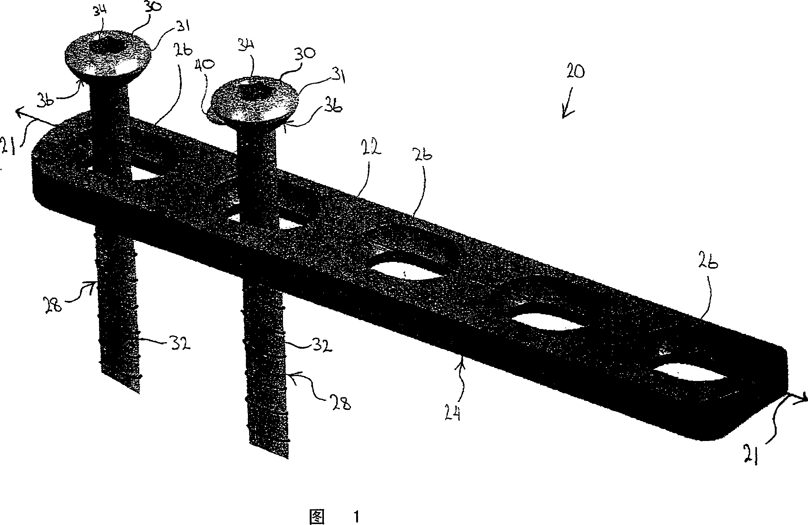
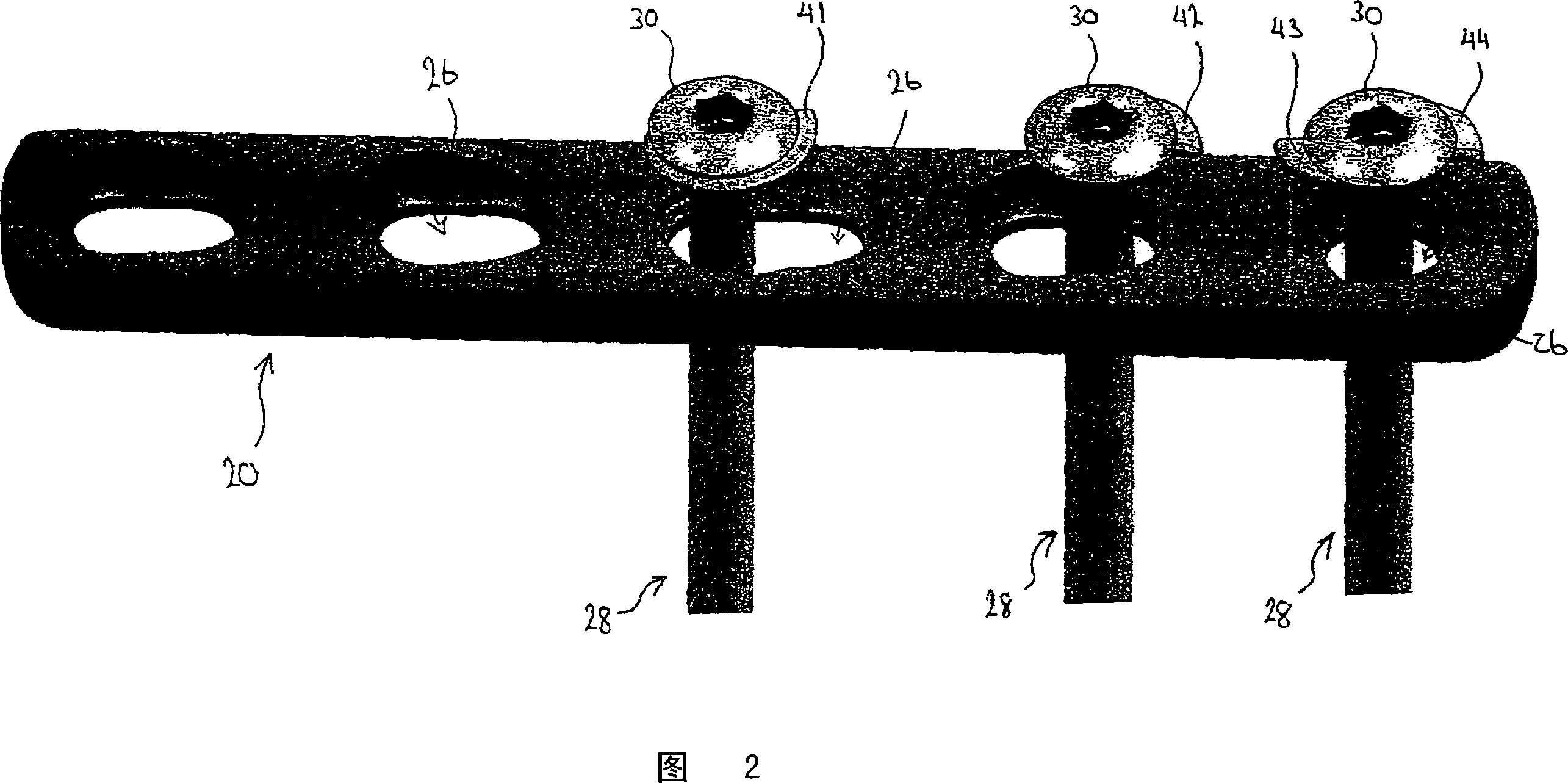
[0028] Referring generally to FIG. 1 , the camming / compression bone plate 20 includes an outwardly facing surface 22 and a bone facing surface 24 opposite the outwardly facing surface 22 . The bone plate may have an elongated shape such that it defines a central longitudinal axis 21 extending the length of the elongated plate. A plurality of holes 26 extend through the bone plate from outward facing surface 22 to bone facing surface 24 . Hole 26 is generally disposed along longitudinal axis 21 , but may be located elsewhere on plate 20 as well. Each of the plurality of holes is configured to receive a bone screw 28 . Both bone plate 20 and bone screw 28 are composed of a biocompatible substance. Examples of such biocompatible substances include: titanium, nickel, cobalt chromium, and other biocompatible substances recognized by those skilled in the art.

[0029] bone screw

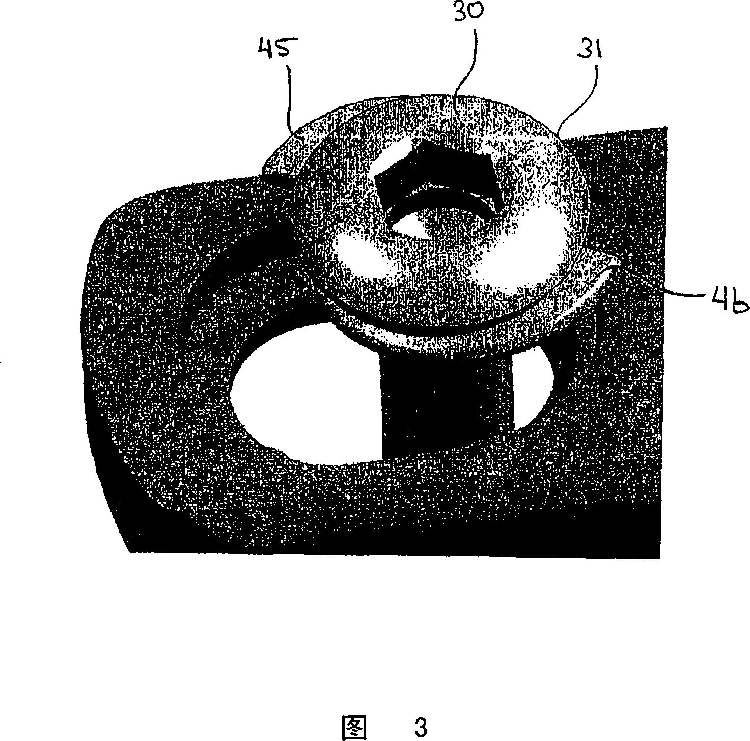
[0030] As shown in FIGS. 1 and 2 , each bone screw 28 generally includes a head 30 having a thread...


PUM


Abstract

A bone plate is disclosed herein. The bone plate generally comprises a bone facing surface, an outward facing surface opposite the bone facing surface, and at least one hole extending through the bone plate from the outward facing surface to the bone facing surface. An arced compression surface is provided within the at least one hole and a cam path is formed on the arced compression surface. The cam path comprises a cam groove that forms an indentation in the arced compression surface. The arced compression surface generally extends 360 DEG or less within the at least one hole. Similarly, the cam path generally extends one revolution or less around the hole upon the arced compression surface. Depending on the type of screw used in association with the bone plate, the bone plate to be used as either a compression plate or a locking plate.

Description

technical field [0001] The present application relates generally to the field of orthopedic surgery, and more particularly to osteosynthetic plates and systems for stabilizing and compressing fractured or otherwise injured bone. Background technique [0002] Osteosynthesis is a surgical procedure that stabilizes and joins the ends of broken bones using mechanical devices such as metal plates, pins, rods, wires, or screws. Bone plates are commonly used in osteosynthesis. Bone plates generally include a bone-contacting surface, an upper surface opposite the bone-contacting surface, and a plurality of holes extending through the plate. The holes in the bone plate are configured to receive bone screws for securing the plate to the bone. [0003] In general, two different types of bone plates have existed in the past. The first type of board is the compression board. The holes formed in the compression plate include compression slopes formed along sides of the holes. These c...

Claims


Application Information

Patent Timeline
Patent Type & Authority Applications(China)
IPC IPC(8): A61B17/80
CPCA61B17/8052A61B17/8014A61B17/8047
Inventor J·F·龙D·D·奥格尔D·J·施泰因伯格
Owner DEPUY PROD INC
Why Eureka
Try Eureka