

Hammer wheel for float mill
A hammer wheel and grinding technology, which is applied in grain processing and other directions, can solve the problems of increasing ineffective power, increased wear of the ring lining plate 1 and eccentric shaft 4, and inertial imbalance, so as to shorten the time and simplify the installation and disassembly process. handy effect
Inactive Publication Date: 2008-03-26
许松柏 +2
View PDF0 Cites 2 Cited by
- Summary
- Abstract
- Description
- Claims
- Application Information
AI Technical Summary
Problems solved by technology
The disadvantages are as follows: the hammer head 3 rotates on the eccentric shaft 4 and has a certain swing. In the state of high-speed motion, there is inertial imbalance, which continuously impacts the ring liner 1, which makes the wear of the ring liner 1 and the eccentric shaft 4 intensified. , increase the invalid power
The hammer head 3 and the eccentric shaft 4 are vulnerable parts and need to be replaced frequently
Method used
View moreImage
Smart ImageViewing Examples

Examples
Embodiment Construction
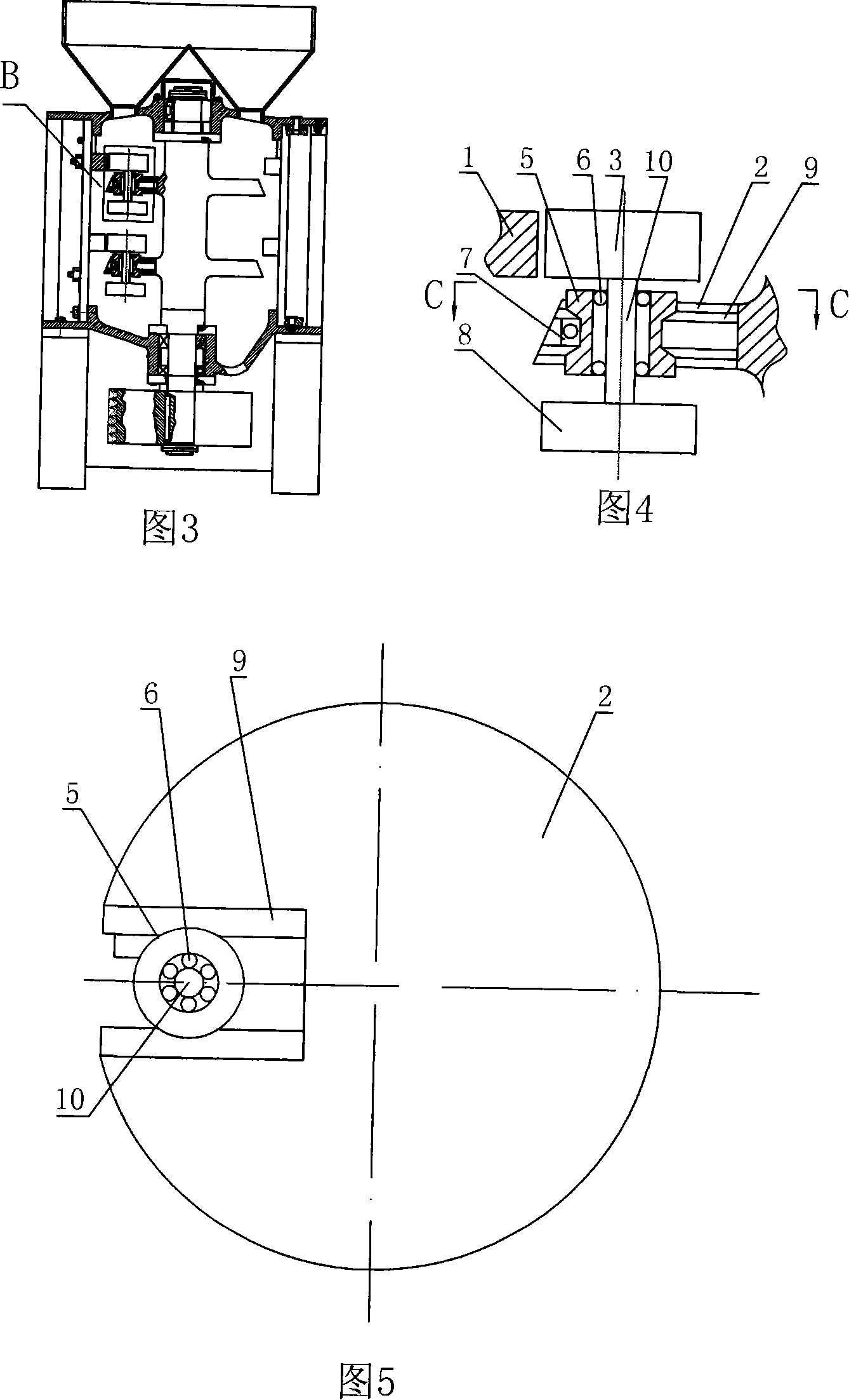
[0019] A hammer wheel of a floating mill, as shown in Figure 3-5. The hammer wheel is installed on the turntable 2, corresponding to the ring liner 1. There are gaps distributed on the corresponding positions of the turntable 2, the two radial sides of the gap are equipped with rails 2, the hammer wheel assembly is installed on the rail 9 and fixed in the gap by the pressure plate 7, the outer edge of the roller 5 matches the shape of the rail 9, Bearing 6 is equipped with in roller 5 inner holes, and tup 3, flywheel 8 are installed on the bearing 6 of roller 5 inner holes by hammer shaft 10.
Login to View More PUM
 Abstract
The present invention relates to a hammer wheel of float-rolling milling machine. The described hammer wheel is mounted on a rotating disk, and is correspondent with a circular ring lining plate, on the correspondent position of said rotating disk a notch is set, on two radial side walls of said notch a guideway is mounted, the hammer wheel assembly is mounted on the guidway and is fixed in the notch interior by means of pressure plate, the external edge of rolling wheel is matched with the form of guideway, in the inner hole of said rolling wheel a bearing is mounted, the hammerhead and fly wheel are mounted on the bearing mounted in the inner hole of said rolling wheel by means of hammer shaft. Said invention also provides the concrete operation method of said hammer wheel.
Description
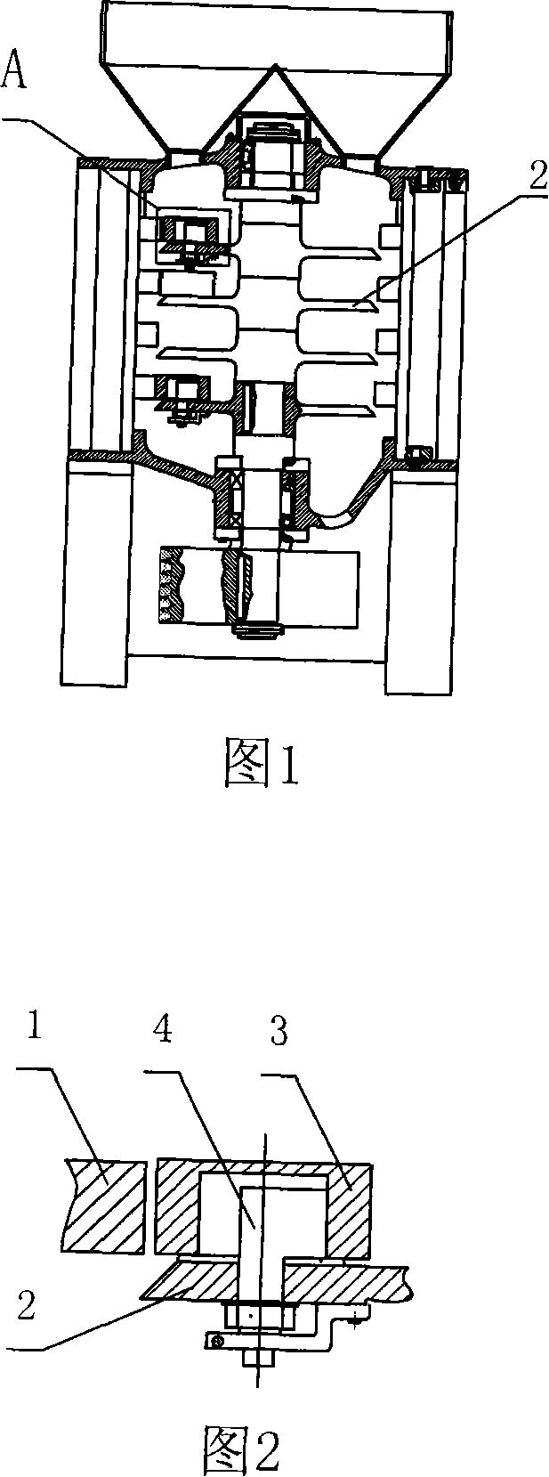
Technical field [0001] The invention relates to a hammer wheel of a floating mill. Background technique [0002] In the prior art, the hammer wheel of the floating mill is installed on the cylindrical eccentric shaft, which can not only revolve but also rotate to a certain extent. The crushing principle is: under the action of centrifugal force, the hammer wheel crushes and crushes the material on the ring liner. Rely on eccentric adjustment to control the thickness of the product. Its structure is shown in Figure 1 and Figure 2, the hammer wheel A is installed on the turntable 2, corresponding to the ring liner 1, the hammer head 3 is installed on the eccentric shaft 4 through its inner hole, the hammer head 3 There is a floating gap between the inner hole and the eccentric shaft 4. The disadvantages are as follows: the hammer head 3 rotates on the eccentric shaft 4 and has a certain swing. In the state of high-speed motion, there is inertial imbalance, which continuousl...
Claims
Login to View More Application Information
Patent Timeline
 IPC IPC(8): B02C15/08
Inventor 许松柏殷作良谭昊
Owner 许松柏