Mortar stirring device

A mortar mixing and external mixing technology, which is applied in the field of mixing machinery, can solve the problems of single mortar flow direction and insufficient mixing of mortar components, and achieve the effect of sufficient mixing and avoiding air bubbles

Inactive Publication Date: 2008-03-26
SANY HEAVY IND CO LTD (CN)
View PDF1 Cites 23 Cited by
  • Summary
  • Abstract
  • Description
  • Claims
  • Application Information

AI Technical Summary

Problems solved by technology

The disadvantage of this twin-shaft mixer is that when the mixing arm and the mixing blade hit the mortar, there is generally a process of stretching out the mortar and exposing it to the air. This process will inevitably bring a large amount of air into the mortar. The air will form many air bubbles in the mixed mortar
But this kind of mortar mixer has only one rotating shaft. When the mixer is working, the rotating shaft can only rotate around the rotating shaft at the center, and the flow direction of the mortar rotation is single. Compared with the twin-shaft mixer, there is insufficient mixing of various components of the mortar. lack of

Method used


Image

  • Mortar stirring device
  • Mortar stirring device
  • Mortar stirring device

Examples


Embodiment Construction

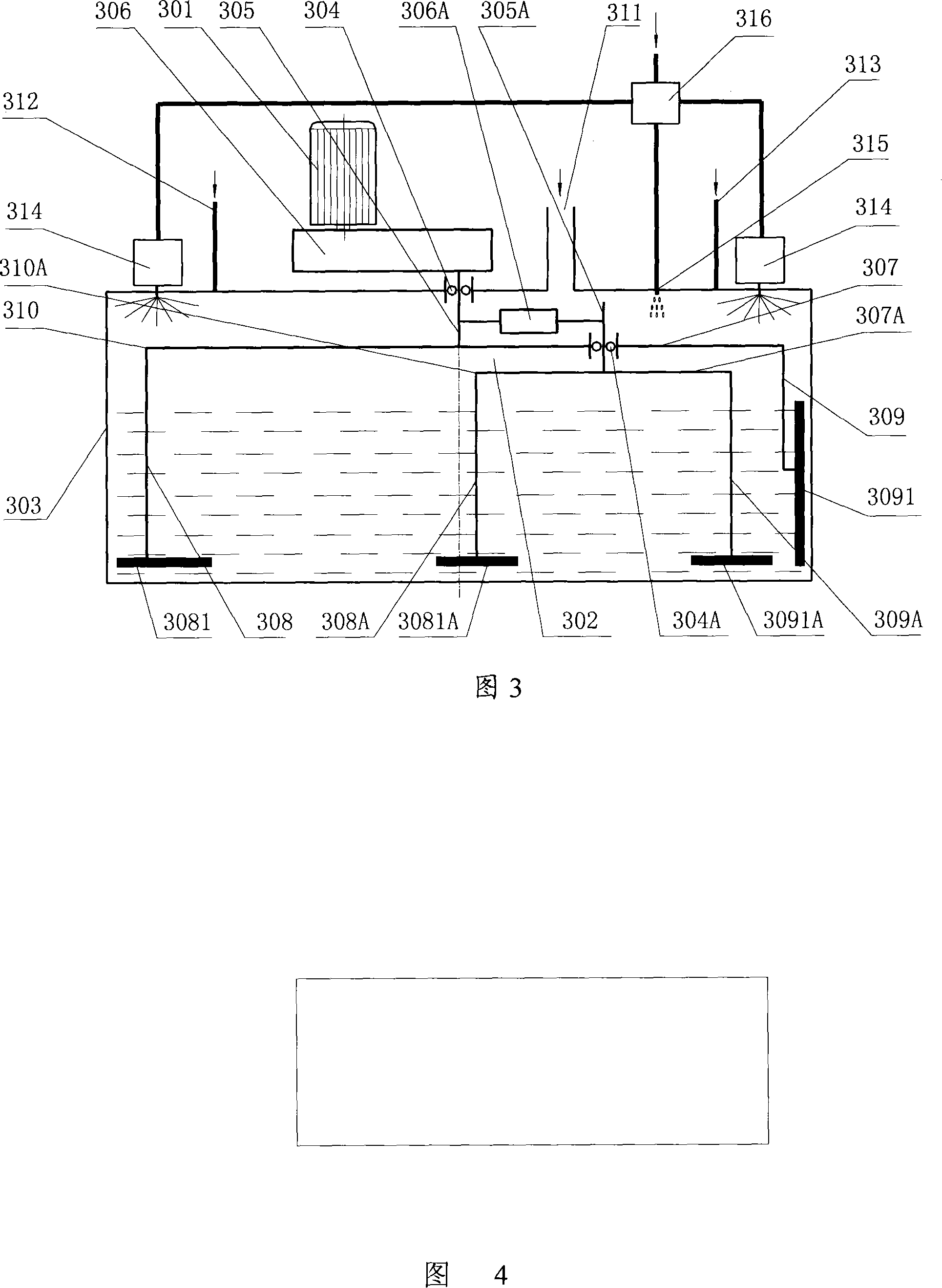
[0027] Please refer to FIG. 3 , which shows the structure of the mortar stirring device provided by the first embodiment of the present invention.

[0028] As shown in FIG. 3 , the mortar stirring device includes a motor 301 , a stirring mechanism 302 , and a bucket 303 . Wherein the material barrel 303 is a cylinder with a top cover, and its interior is used to place mortar; the material barrel 303 is also a base for placing other mechanisms. Motor 301 is installed on the top cover of material bucket 303, and this top cover also has the opening of various feeding pipes, water inlet pipe etc., and connects corresponding pipeline. A first bearing 304 with a vertical axis is installed in the center of the top cover of the bucket 303 , and the vertically arranged main shaft 305 of the stirring mechanism 302 is installed on the first bearing 304 . The first transmission mechanism 306 connects the motor 301 and the main shaft 305 of the stirring mechanism 302 , and the function of...


PUM


Abstract

The mortar stirring apparatus includes one motor, one stirring mechanism, and one cylindrical material barrel. The stirring mechanism is one planetary one including one outer stirring arm and inner stirring arm, the outer stirring arm is fixed to the top or the bottom of the material barrel through the vertically installed main rotation shaft rotating under the drive of the motor through the first driving mechanism, and the inner stirring arm is mounted on the outer stirring arm through one driven rotation shaft. While the outer stirring arm rotates, one second driving mechanism transfers the rotation of the main rotation shaft to the driven rotation shaft, so the inner stirring arm rotates around the driven rotation shaft while revolving with the outer stirring arm. The planetary stirring mechanism has well stirring to the mortar. In addition, the stirring blades always stir under mortar surface without carrying in air.

Description

technical field [0001] The invention relates to a mixing machine, in particular to a mortar mixing device applied in the construction field. Background technique [0002] In the field of construction, various mixing machines are widely used. For example, in the process of building high-speed railway (road) roads, a special asphalt cement mortar (also known as CA mortar or BZM mortar) must be mixed. Mortar is generally processed by a twin-shaft mixer. The structural principle of the twin-shaft mixer is shown in Figure 1. Its mixing mechanism has two first rotating shafts 101 and second rotating shafts 102 placed horizontally and on the same horizontal plane. shown) to drive the rotation. The ends of the two rotating shafts are respectively equipped with a first stirring arm 103 and a second stirring arm 104 perpendicular thereto, and the above stirring arms rotate around their corresponding rotating shafts respectively, and the ends of the rotating arms are respectively fix...

Claims


Application Information

Patent Timeline
Patent Type & Authority Applications(China)
IPC IPC(8): B28C5/16
Inventor 黄向阳邵满元
Owner SANY HEAVY IND CO LTD (CN)
Why Eureka
Try Eureka