Backlight module

A backlight module, bump technology, applied in optics, nonlinear optics, instruments, etc., can solve the problems of increased production cost of optical film, material waste, etc.

Active Publication Date: 2008-03-26
AU OPTRONICS (XIAMEN) CORP +1
View PDF1 Cites 5 Cited by
  • Summary
  • Abstract
  • Description
  • Claims
  • Application Information

AI Technical Summary

Problems solved by technology

As a result, the production cost of the optical film will increase accordingly, and at the same time, it will cause waste of materials

Method used


Image

  • Backlight module
  • Backlight module
  • Backlight module

Examples


Embodiment Construction

[0031] The following will clearly illustrate the spirit of the present invention with the accompanying drawings and detailed descriptions. After any person with ordinary knowledge in the art understands the preferred embodiments of the present invention, he can change and modify it by the technology taught in the present invention. without departing from the spirit and scope of the present invention.

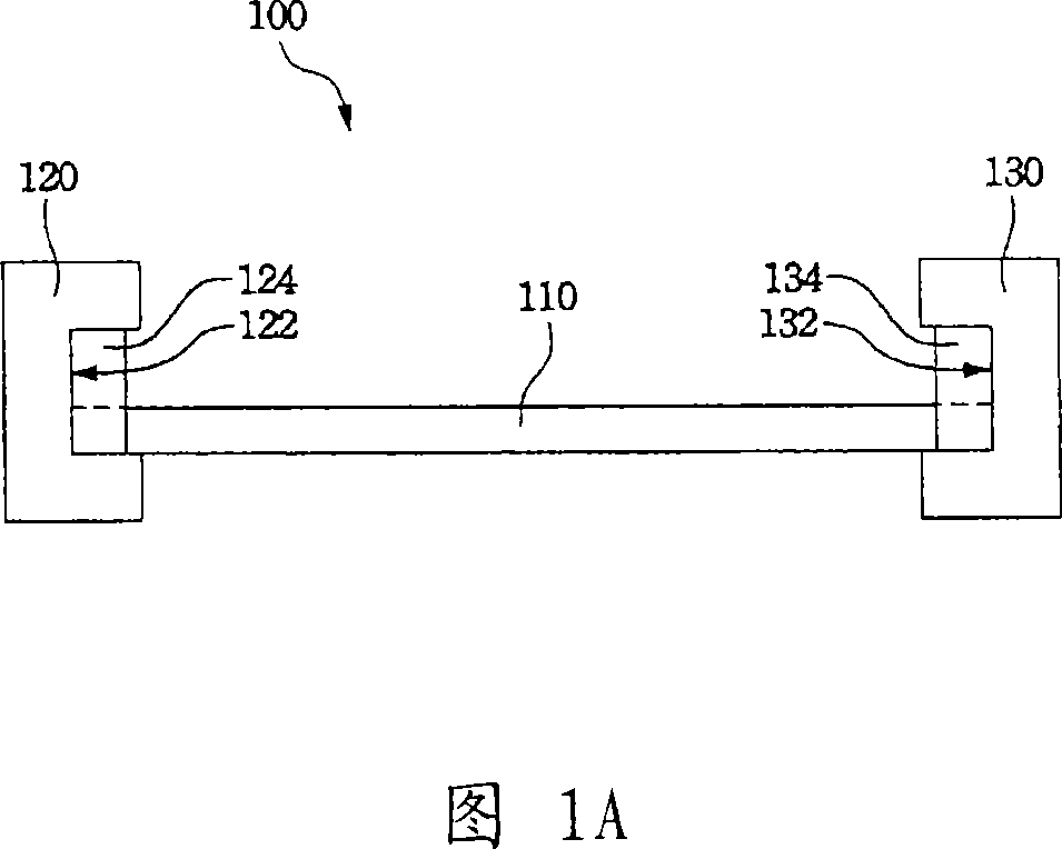
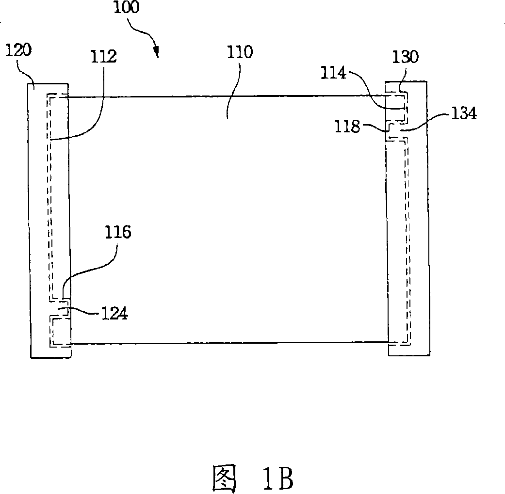
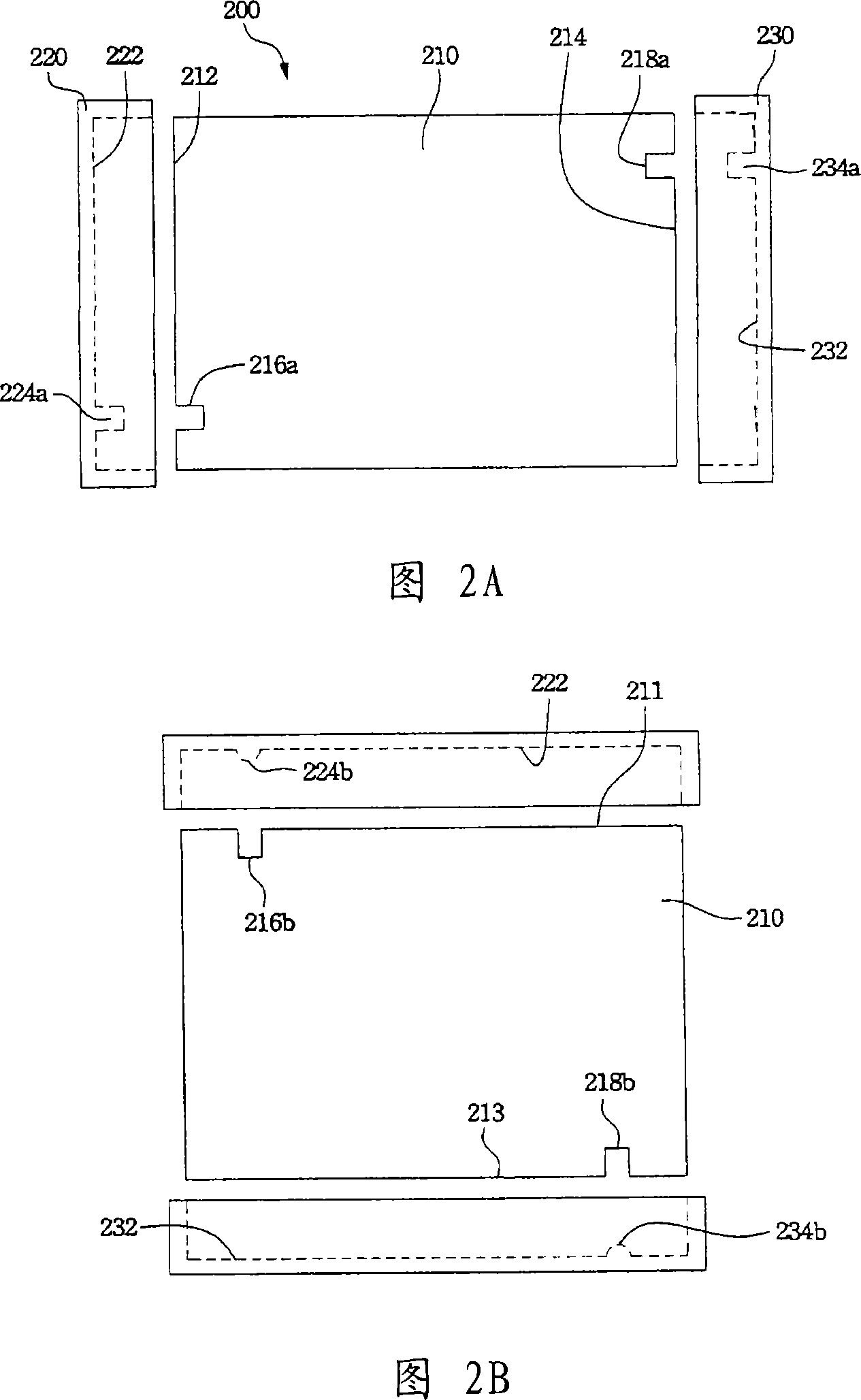
[0032] A common backlight module includes optical films such as a light guide plate, a reflector plate, a diffuser plate, and a diamond lens, a backlight source, an outer frame, and a back plate. For the convenience of assembly, the optical film is mostly inserted into the groove on the side of the outer frame in the way of side insertion. However, when assembling the optical film, it is difficult to judge the front and back of the optical film with the naked eye. Therefore, if you are not careful during assembly, it may be installed on the reverse side, which will affect the op...


PUM


Abstract

This invention discloses a sort of back-light module, and it consists of an optics film and an outline border. The optics has one side at least, and two gaps which are formed in the side and they locate in the different height apart. The outline border has a flute in order to contain the optics film in the flute. There have two projections which correspond the gap in the flute, and the projection locates in the gap when the optics film is packed in the outline border.

Description

technical field [0001] The invention relates to a backlight module, and in particular to a backlight module of a liquid crystal display. Background technique [0002] With the advancement of optical technology and semiconductor technology, liquid crystal displays have been widely used in display devices of electronic products. Liquid crystal display has the advantages of high image quality, small size, light weight, low voltage drive, low power consumption and wide application range, so it has been widely used in portable TVs, mobile phones, video recorders, notebook computers , Desktop monitors, and projection TVs and other consumer electronics or computer products have become the mainstream of displays. [0003] The liquid crystal display panel in the liquid crystal display itself is not a light-emitting display element, and the required light source needs to be provided by the backlight module. Since the performance of the backlight module will directly affect the quali...

Claims


Application Information

Patent Timeline
Patent Type & Authority Applications(China)
IPC IPC(8): G02F1/13357G02F1/1333G02F1/1335
CPCG02F2001/133317G02F2001/133322G02F1/133606G02F1/133608G02F1/133317G02F1/133322
Inventor 卢仁生任伟
Owner AU OPTRONICS (XIAMEN) CORP
Why Eureka
Try Eureka