

Precision rotation positioning platform based on compliant mechanism
Patent Information
- Authority / Receiving Office
- CN · China
- Current Assignee / Owner
- SOUTH CHINA UNIV OF TECH
- Publication Date
- 2008-03-26
- Estimated Expiration
- Not applicable · inactive patent
Smart Images
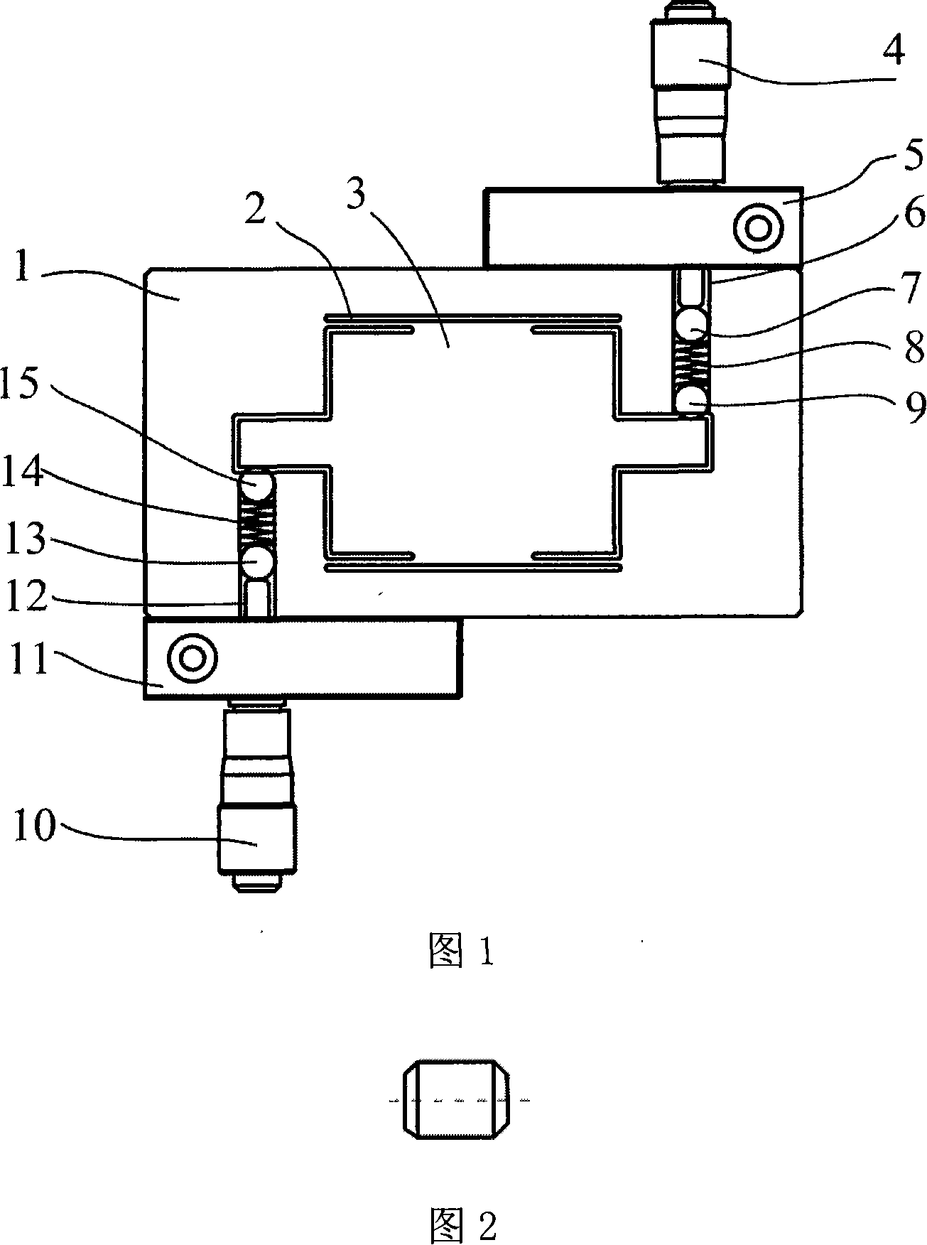
Figure 1
Abstract
Description
technical field
[0001] The invention relates to a precision rotary positioning platform based on a compliant mechanism, in particular to a compliant precision positioning platform capable of finely adjusting the angle of rotation around a Z axis. Background technique
[0002] At present, the rotary positioning platform is usually driven by a motor, or driven by a worm gear and a worm screw. The center of this platform usually has a shaft, and the worktable rotates around the shaft under the drive of an external force. Since these platforms are all rigid mechanisms, there is a certain fit gap, and the rotation accuracy can generally only reach the milliradian level. With the development of precision positioning technology, there are higher requirements for the positioning accuracy of the rotary positioning platform. The positioning accuracy of the platform is required to reach the micro-radian level, and the traditional rigid rotary platform is difficult to meet the requireme...