Clamp for holding vessels

A clamp and container technology, applied in the field of clamps for holding containers, can solve the problems of unsatisfactory, difficult cleaning and disinfection of the cavity, complicated structure of the grabbing arm, etc., and achieve the effect of achieving shape stability

Inactive Publication Date: 2008-03-26
KRONES AG
View PDF6 Cites 22 Cited by
  • Summary
  • Abstract
  • Description
  • Claims
  • Application Information

AI Technical Summary

Problems solved by technology

[0003] However, this clamp has the disadvantage that the construction of the gripper arms is relatively complex, since an additional leaf spring must be installed in each gripper arm, and in addition, due to the presence of this leaf spring, an inaccessible cavity is created, said Cavities are not easily cleaned an...

Method used


Image

  • Clamp for holding vessels
  • Clamp for holding vessels

Examples


Embodiment Construction

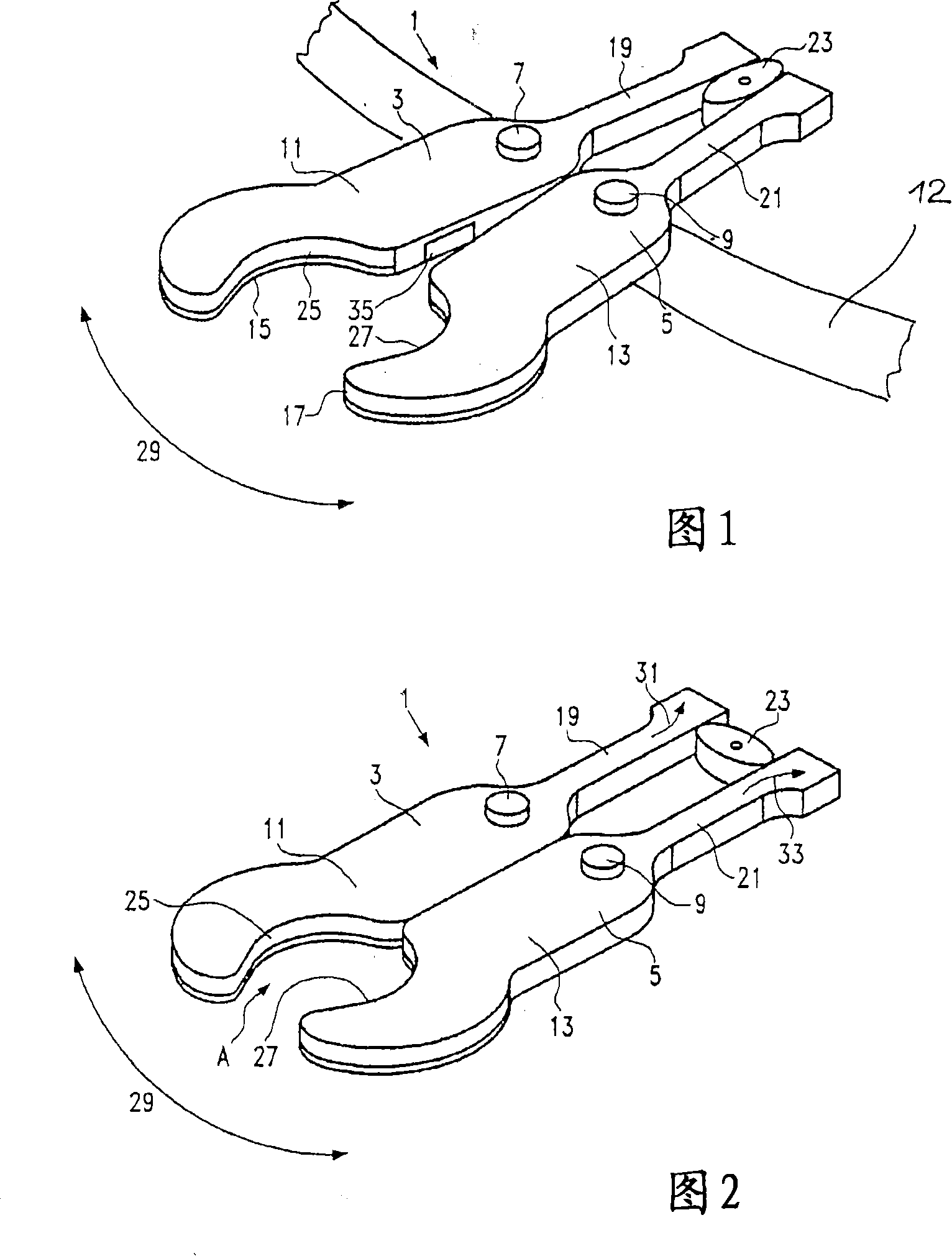
[0021] A gripper 1 for gripping containers, in particular bottles, is shown in FIGS. 1 and 2 . The gripper 1 is generally used for conveying and sorting containers in conveying stars, which are used, for example, at the outlet of bottle handling machines such as filling or inspection machines.

[0022] FIG. 1 shows a transfer star 12 on which the gripper 1 is rotatably fastened by means of pins 7 , 9 . The teleportation star is preferably made of stainless steel, but other materials are also conceivable. The fixation of the clamp 1 is obviously not limited to transporting stars. Of course, fastening to chain links, belts and other conveying devices is also possible.

[0023] In the first embodiment the gripper 1 comprises two mirror-symmetrical gripper arms 3 and 5 . The gripper arms 3 and 5 are mounted rotatably on a pin 7 and 9, respectively. Each one-piece clamping arm 3 , 5 has a gripper arm 11 or 13 , the ends of which are each curved in order to be able to enclose th...


PUM

PropertyMeasurementUnit
Elastic modulusaaaaaaaaaa

Abstract

The invention relates to a clamp for holding vessels, in particular, bottles in vessel transport machines, comprising two clamping arms (3, 5, 51) which can be displaced in relation to each other in order to open and close the vessels. Each clamping arm (3, 5, 51) comprises a gripping arm (11, 13, 53) and at least one clamping arm (3, 5, 51) comprises a counter arm (19, 21, 55). The vessels are centred in an exact manner and the pressure forces can be absorbed in order to simplify the construction thereof. The clamping arm is embodied as a single piece with a gripping arm and a counter arm such that the gripping arm is dimensionally stable and the counter arm is elastic.

Description

technical field [0001] The invention relates to a gripper for gripping containers, especially bottles, in a container transfer and handling machine, comprising at least two gripper arms movable relative to each other to open and close, wherein each gripper arm has a gripper arms and at least one clamp arm has a corresponding arm. Background technique [0002] Such grippers for gripping or gripping containers are known, for example, from EP 09 39 044 B1, EP 07 262 16 B1 and EP 07 43 26 7 B1. The clip known from EP 09 39 044 is economically satisfactory. Such a clamp comprises two metal clamp arms which are arranged so as to be pivotable relative to each other. On the container side of the pivot axis there is a gripping area and on the other side of the pivot axis there is an operating area for opening and closing the arms. A leaf spring is additionally formed where the control cam contacts the actuating area of ​​the pick-up arm. It is used to compensate for different con...

Claims


Application Information

Patent Timeline
IPC IPC(8): B08B9/42B67C3/24B65B21/12B65G47/84B25J15/02
CPCB65G47/847B65G2201/0244B08B9/426
Inventor G·策普夫R·格勒茨尔
Owner KRONES AG
Why Eureka
Try Eureka