Flexible led array

A flexible substrate and heat dissipation pad technology, applied in the field of flexible LED arrays, can solve the problems of inability to achieve heat dissipation, large units, loss of flexibility, etc.

Inactive Publication Date: 2008-03-26
KONINKLIJKE PHILIPS ELECTRONICS NV
View PDF1 Cites 10 Cited by
  • Summary
  • Abstract
  • Description
  • Claims
  • Application Information

AI Technical Summary

Problems solved by technology

Such a solution can only dissipate heat from the LED in one direction and cannot achieve the required he

Method used


Image

  • Flexible led array
  • Flexible led array
  • Flexible led array

Examples


Embodiment Construction

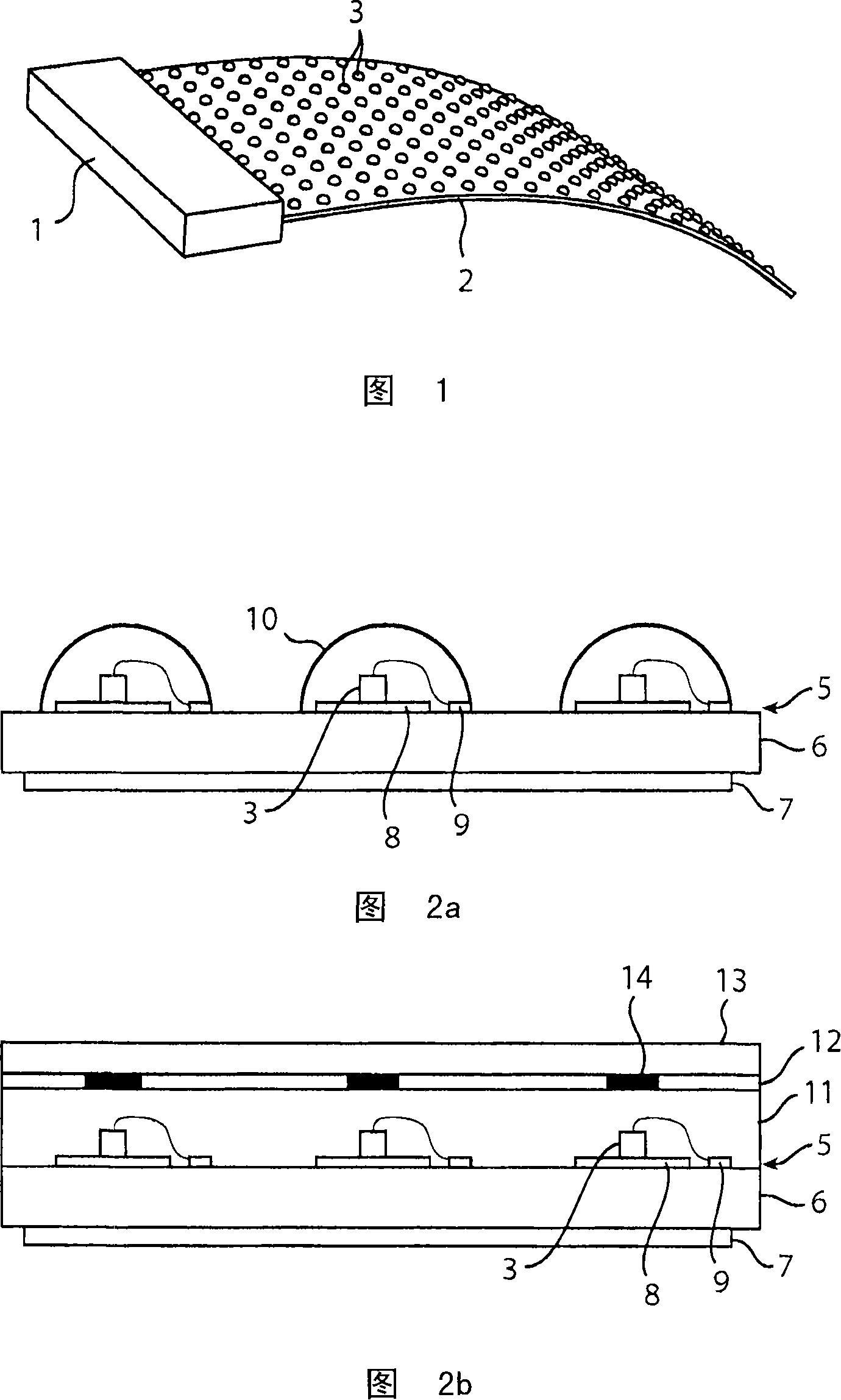
[0022] The light emitting device shown in Fig. 1 includes: a control unit 1, a flexible substrate 2, and a plurality of LEDs 3 arranged on the substrate. The control unit 1 contains any driver circuits, interfaces, connectors, etc. needed to connect the device to a power source and drive the LED to emit light. Since the control unit keeps all control circuits close to each other, the circuits are well protected. However, the control unit forming part of the flexible device is rigid.

[0023] As an alternative, the control circuits may be distributed on the substrate, for example along the sides of the substrate. This allows for a fully flexible device, but does not result in optimal physical protection of the components.

[0024] The power supply of the device can be conventional, with a connector or even with batteries contained in the control unit 1 . However, it may be beneficial to provide a power source that is not connected. For example, capacitive or inductive power...


PUM


Abstract

A light emitting device, comprising a flexible substrate (2) with a single, structured conductive layer (5), and a plurality of LEDs (3) arranged on said substrate (2), said structured conductive layer (5) forming electrodes for driving said LEDs (3). The structured conductive layer comprises a plurality of heat dissipating pads (8), each having an area significantly larger than the area of each LED (3), and each LED (3a) is thermally connected to at least one of said pads (8a), and electrically connected in series between two pads (8a, 8b). Through this design, each LED is thermally connected to a relatively large heat dissipating area, and the thermal energy built up in the LED will be distributed over this area, and then dissipated upwards and downwards from this area. As the addressing can be handled by a single conducting layer, the flexibility of the substrate is improved compared to multilayer substrates. By connecting each LED in series between two pads, a very large portion of the conducting layer can be used for the pads, and very little area needs to be occupied by conducting tracks, which otherwise may be a problem with single layer designs.

Description

technical field [0001] The present invention relates to flexible LED arrays, and more particularly, the present invention relates to light emitting devices comprising a plurality of LEDs arranged on a flexible substrate having a single structured conductive layer for Form the electrodes that drive the LEDs. Background technique [0002] A flexible lighting unit is disclosed in US2003 / 0067775. The unit includes a multi-layer substrate with multiple red, green, and blue LEDs, each color connected in series. [0003] One problem commonly associated with multiple LED devices, especially flexible LED arrays, is heat dissipation. If satisfactory treatment is not carried out, the temperature of the LED will rise, resulting in a decrease in light efficiency. In the unit described in US2003 / 0067775, heat dissipation is handled by a heat sink structure fixed to a heat sink plate at the rear of the base plate. Such a solution can only dissipate heat from the LED in one direction an...

Claims


Application Information

Patent Timeline
IPC IPC(8): H01L33/00H01L25/075H01L33/64
CPCH05K1/189H01L2924/30107H05K1/0203H01L2224/48091F21K9/00H05B33/26H01L33/647H01L25/0753F21Y2105/10F21Y2115/10H01L2924/00
Inventor M·A·德萨姆伯M·西肯斯H·J·埃金克
Owner KONINKLIJKE PHILIPS ELECTRONICS NV
Why Eureka
Try Eureka