
Flange quick-changing drill jig

A drilling jig and flange technology, applied in the field of machinery, can solve problems such as difficult positioning of water pump flanges, and achieve the effect of meeting the needs of large-scale production, simple and fast operation, and convenient use

Inactive Publication Date: 2008-04-02
SHANGHAI EAST PUMP(GRP) CO LTD
View PDF0 Cites 12 Cited by
  • Summary
  • Abstract
  • Description
  • Claims
  • Application Information

AI Technical Summary

Problems solved by technology

[0003] The purpose of the present invention is to provide a flange quick-change drilling jig, which solves the technical problem of difficult positioning of the water pump flange in the prior art during drilling

Method used


Image

  • Flange quick-changing drill jig

Examples


Embodiment Construction

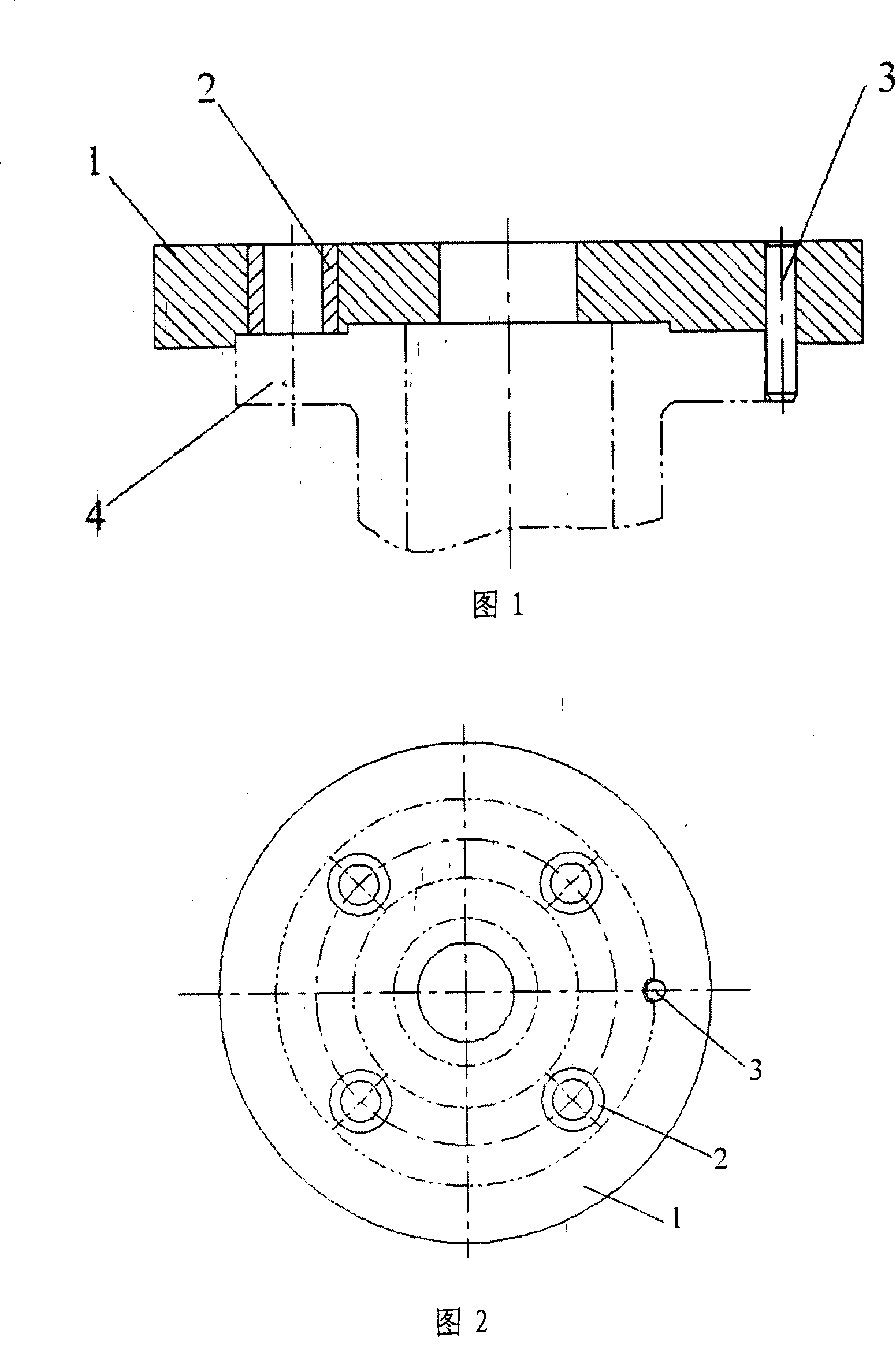
[0012] As shown in Figures 1 and 2, the flange quick-change drill die of the present invention is composed of a metal disc member 1, wherein the metal disc member 1 is provided with a plurality of through holes, and any one of the The axial direction of the through hole is parallel to the axial direction of the metal disc member 1, and a drill sleeve 2 is fixedly arranged in any through hole, and any one of the drill sleeves 2 is a cylindrical tubular member, and the metal disc member At least one positioning pin hole is provided in 1.

[0013] Further, a positioning pin 3 is provided in the positioning pin hole.

[0014] Further, the diameter of the positioning pin is 8 mm.

[0015] Further, four drill sleeves 2 are provided in the metal disc member 1.

[0016] The working principle of the present invention is: a circular arc notch is cast on the blank 4 of the flange to be processed, the metal disc member 1 is placed on the end face of the flange during processing, and the posit...


PUM

PropertyMeasurementUnit
Diameteraaaaaaaaaa

Abstract

The invention provides a flange quick-change drill plate and consists of a metal disk component. The metal disk component is provided with a plurality of through holes inside, axial direction of any through hole is parallel to that of the metal disk component, a drill bush is fixedly arranged in any through hole, any drill bush is a cylinder tubular component, and at least one positioning pin hole is arranged in the metal disk component. A positioning pin is arranged in the positioning hole. An arc-shaped nick is casted on the rough of an awaiting flange, the metal disk component is arranged on the end surface of the flange when in processing, the positioning pin is arranged in the arc-shaped nick of the flange rough, a spigot of the metal disk component matches with the spigot of the flange rough, and then drilling of the flange rough can be conducted with the drill bush. The invention has simple operation and easy use and can meet the requirement of large scale production, moreover, bias of processed hole site is less than 1mm and can meet the requirement of interchangeability.

Description

Technical field: [0001] The invention relates to the field of machinery, in particular to pumps, in particular to an auxiliary processing device for flanges in water pumps, and in particular to a flange quick-change drilling jig. Background technique: [0002] The flange in the water pump needs to be positioned during drilling. In the prior art, manual marking is used for positioning, or a special drilling jig is used for positioning. The special drilling jig is positioned at the rear flange of the pump body, the structure is complicated and the operation is inconvenient. However, the manual marking speed is too slow, the labor intensity is high, the production efficiency is not high, and it is not suitable for modern large-scale production. Summary of the invention: [0003] The purpose of the present invention is to provide a flange quick-change drilling jig, which is to solve the technical problem of difficult positioning of the water pump flange during drilling processing in...

Claims


Application Information

Patent Timeline
IPC IPC(8): B23B47/28
Inventor 吴永旭冉仕兵
Owner SHANGHAI EAST PUMP(GRP) CO LTD
Learn More