Water heater

A water heater and water inlet technology, which is applied in fluid heaters, lighting and heating equipment, etc., can solve the inconvenience of production and after-sales maintenance, the display cover of the anti-electric wall and the incorrect connection of the inlet and outlet water insulation pipes, and the inability to remove the magnesium rod And other issues

Active Publication Date: 2008-04-02
HAIER GRP CORP +1
View PDF1 Cites 6 Cited by
  • Summary
  • Abstract
  • Description
  • Claims
  • Application Information

AI Technical Summary

Problems solved by technology

Then inject foaming material (liquid) into the foaming layer 2' between the outer shell 1' and the inner tank 3', and the mixed foaming material will expand rapidly in a short time. Obviously, the existing process determines the foaming The material can only be injected into the foam layer from one direction, which causes the unbalanced force on the inner barrel and the lower head of the inner tank during the foaming process, so the position of the inner tank 3' will shift. When the foam material solidifies Afterwards, the shell water inlet 11', the water outlet 10' and the water inlet 4' and the water outlet 5' will not be concentric (as shown in Figure 2), which will cause considerable trouble to the subsequent processes, such as water inlet The electrodes on the insulating tube will be cut by the casing, the magnesium rod cannot be installed, the electric wall installation cover and the water inlet and outlet insulation pipes are not aligned correctly, not directly below the water heater, and the magnesium rod cannot be removed when the magnesium rod is replaced after sales. happened
Cause some inconvenience to production and after-sales maintenance

Method used


Image

  • Water heater
  • Water heater
  • Water heater

Examples


Embodiment Construction

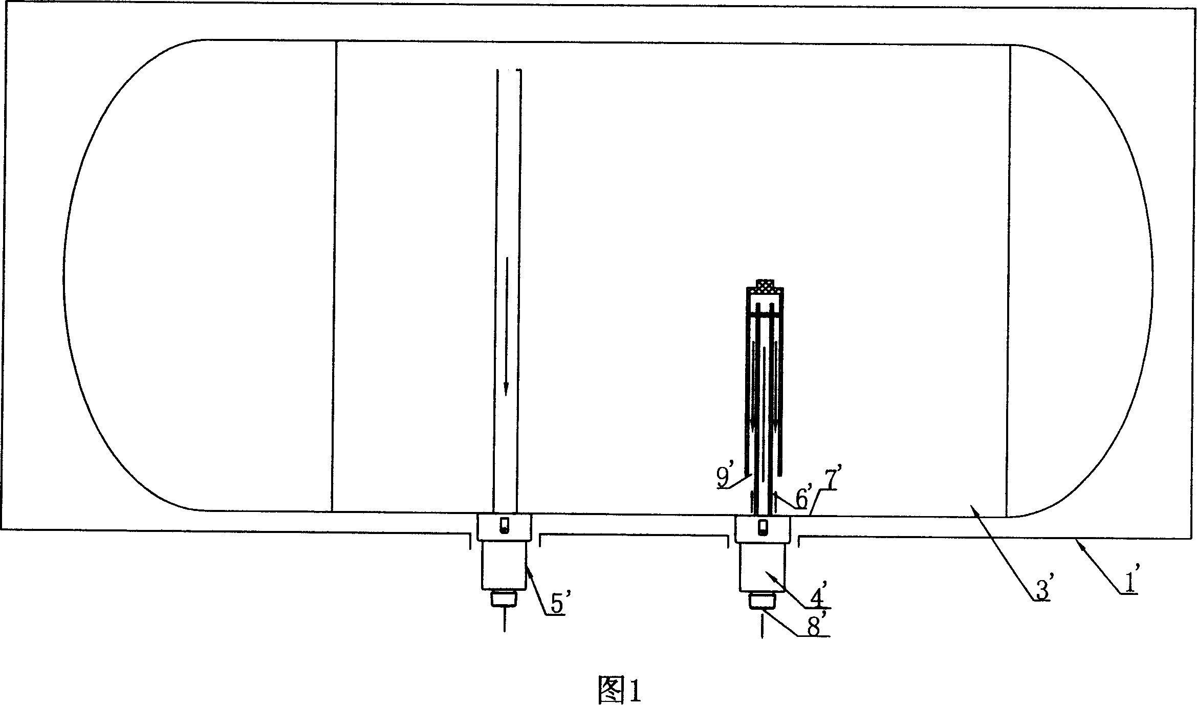
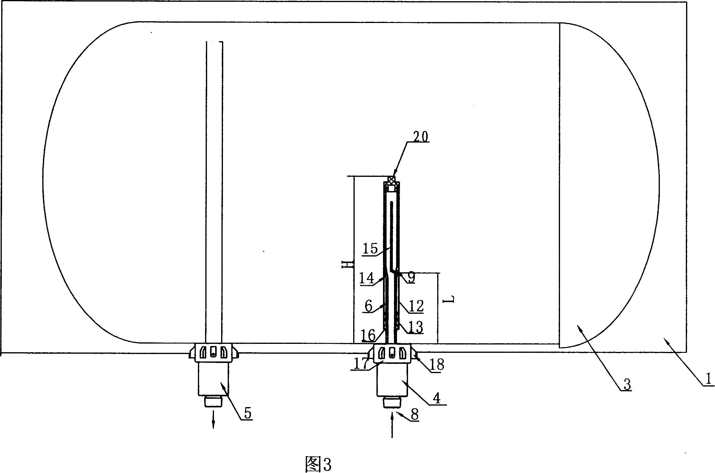
[0031] As shown in Figure 3 and Figure 6, the water heater according to the present invention includes a shell 1, a foam layer 2, an inner tank 3, a water inlet insulating pipe and a water outlet insulating pipe 5, and the outer shell is provided with a water inlet 11 and a water outlet 10. The water inlet insulating pipe includes the water inlet pipe 4 arranged outside the inner tank of the water heater, the inner pipe 6 arranged in the inner tank 3 and connected with the water inlet pipe 4, and the water inlet pipe 4 and the inner pipe 6 are connected through a screw head 17, Its main feature is that at least two positioning ribs 18 that can fix the liner 3 without shifting are provided on the screw heads of the water inlet pipe and the water outlet pipe corresponding to the water inlet hole 11 and the water outlet hole 10 of the water heater shell. There are 6 places.

[0032] As shown in Fig. 3 to Fig. 5, the water inlet insulating pipe described in the present invention, ...


PUM


Abstract

The present invention discloses a water heater, comprising a shell, a foaming layer, a liner, a water inlet insulating pipe and a water outlet insulating pipe, wherein, a water inlet hole and a water outlet hole are arranged on the shell; the water inlet insulating pipe comprises a water inlet pipe arranged outside the liner of a heater, an inner pipe which is arranged inside the liner and communicated with the water inlet pipe, as well as a casing pipe sleeved outside the inner pipe; the water inlet pipe and the inner pipe are communicated through screws; a gap is formed between the inner pipe and the casing pipe. The present invention is characterized in that: the peripheral wall of the casing pipe is provided with dispersive type water outlet holes; the gap between the lower end of the casing pipe and the inner pipe is provided with a positioning lug boss, which can reinforce the casing pipe and stem water impact to the inner wall of the liner, thus inlet water can have impact force relieved in the gap and then enter into the liner from the dispersive water outlet holes. The present invention is provided with a plurality of positioning ribs on the screws of the water inlet insulating pipe and the water outlet insulating pipe corresponding to the water outlet holes on the shell, which avoids the eccentricity of the water inlet-outlet pipes and the water inlet-outlet holes on the shell.

Description

technical field [0001] The invention relates to a water heater, in particular to a water heater with a water inlet insulating pipe capable of alleviating the impact force of water inlet and positioning the inner container. Background technique [0002] At present, with the improvement of people's living standards, water heaters have entered thousands of households. Although there are many types of water heaters, most of them have water storage tanks and water inlet and outlet pipes. However, there are still many problems in the existing water inlet pipes. First: The water injection process of the existing closed water storage water heater is: cold water enters the water inlet pipe 4' from the water inlet 8' of the water inlet pipe along the water path (the direction of cold water in the figure) as shown in Figure 1, and then flows from the water inlet pipe outlet 9' out, into the inner tank 3'. Due to the pressure of the water inlet (generally tap water) (the pressure of ta...

Claims


Application Information

Patent Timeline
Patent Type & Authority Applications(China)
IPC IPC(8): F24H9/14
Inventor 孙京岩王任华孙强蔡想周
Owner HAIER GRP CORP
Why Eureka
Try Eureka