Transverse connecting rod for vehicle

A technology of transverse link and vehicle, which is applied in the direction of vehicle components, cantilever mounted on the pivot, suspension, etc., which can solve the problem of demanding space and achieve the effect of improving force transmission

Inactive Publication Date: 2013-10-30
FORD GLOBAL TECH LLC
View PDF7 Cites 1 Cited by
  • Summary
  • Abstract
  • Description
  • Claims
  • Application Information

AI Technical Summary

Problems solved by technology

However, since the connection points of the transverse links connecting the legs are by their nature locate

Method used


Image

  • Transverse connecting rod for vehicle
  • Transverse connecting rod for vehicle
  • Transverse connecting rod for vehicle

Examples


Embodiment Construction

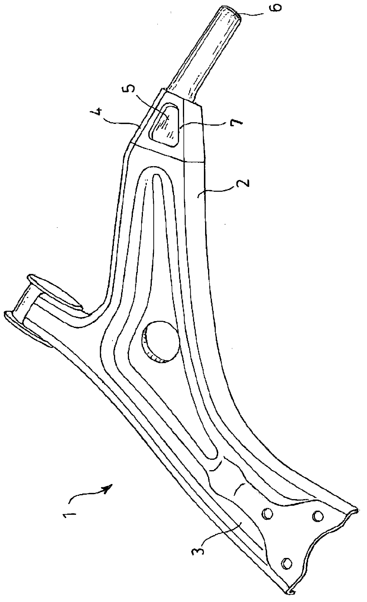
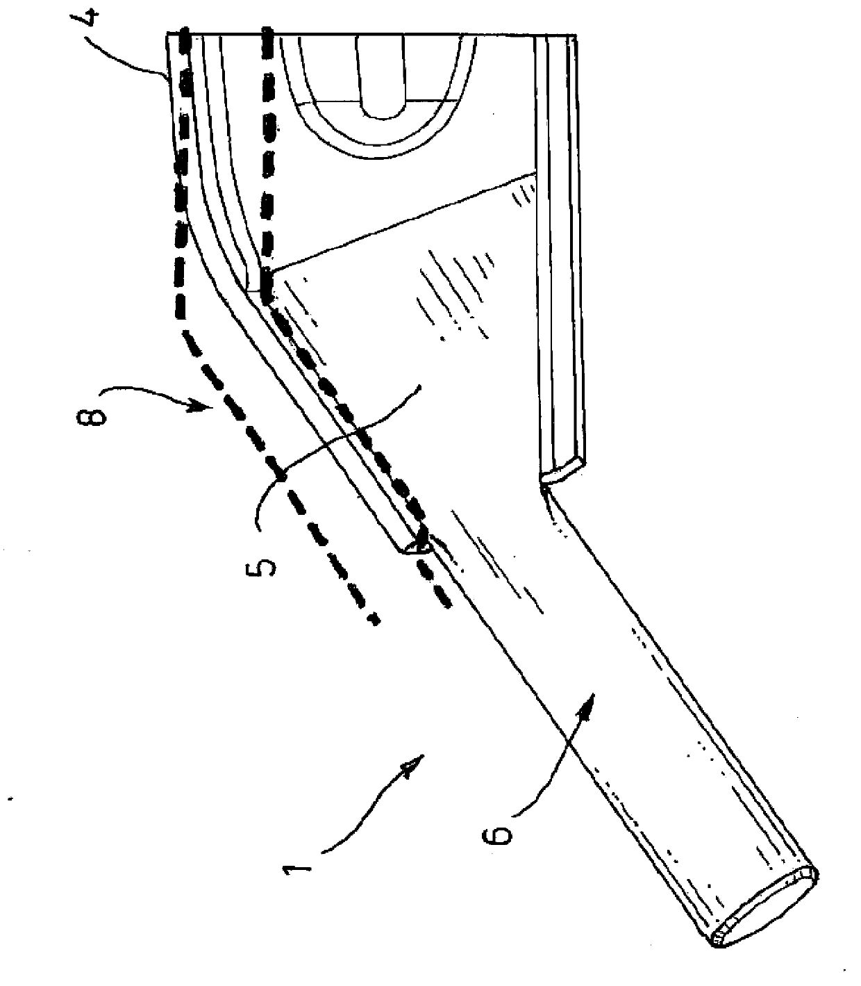
[0040] figure 1 A perspective view of an exemplary embodiment of a transverse link 1 in the form of a monocoque according to the invention is shown. The transverse link 1 has a connection leg 2 for connection to a body (not shown) and a wheel leg 3 for connection to a wheel carrier (also not shown). In this regard, figure 1 The connecting leg 2 and the wheel leg 3 in the transverse link 1 shown in are formed substantially in an L-shape. The connection leg 2 has a connection point 4 to which an anchor 5 of a substantially pin-shaped bearing journal 6 can be connected in a positionally secure manner. From figure 1 It can likewise be seen in the figure that the connecting leg 2 has a recess 7 in the region of the connecting point 4 . The notch 7 is used to allow from figure 1 The side (upper side) of the transverse link 1 shown enters the anchor 5 of the bearing journal 6 located below it, so that this anchor 5 can also be welded from the upper side of the transverse lin...


PUM


Abstract

The invention relates to a transverse connecting rod for a vehicle, which comprises a connecting support leg (2) to be connected with the body of a vehicle, and a wheel support leg (3) to be connected with a wheel carrier. The connecting support leg (2) is provided with at least one connecting point (4) by which an anchoring portion (5) of a pin-shaped bearing journal (6) is connected securely in position. The anchoring portion (5) of the pin-shaped bearing journal (6) is flattened.

Description

technical field [0001] The invention relates to a transverse link for a vehicle, in particular a motor vehicle. Background technique [0002] Transverse linkages of the described type are exposed to complex dynamic loads during braking, acceleration and cornering maneuvers of the vehicle and therefore place correspondingly high demands on structural stability, especially in a certain direction of force action. However, the oscillating masses in the wheel suspension must be kept as low as possible. This creates a need for lightweight design, which is opposed to high structural stability. [0003] Transverse links known in the prior art are generally manufactured as castings or sheet metal parts. In the latter case, the connecting rod may be formed from a single sheet metal piece (so-called monocoque form). However, it is also possible to form the connecting rod from several sheet metal parts joined together. In order to achieve greater rigidity, in the case of a shell des...

Claims


Application Information

Patent Timeline
IPC IPC(8): B60G7/00
CPCB60G2206/122B60G2206/8201B60G7/001
Inventor 克里斯托夫·迈耶西奥·屈佩尔斯
Owner FORD GLOBAL TECH LLC
Why Eureka
Try Eureka