Device and method for control signal transmission in variable band width system

A technology for control signaling and transmission control, applied in wireless communication, communication between multiple stations, network traffic/resource management, etc., to reduce the bit overhead

Inactive Publication Date: 2008-04-02
BEIJING SAMSUNG TELECOM R&D CENT +1
View PDF0 Cites 29 Cited by
  • Summary
  • Abstract
  • Description
  • Claims
  • Application Information

AI Technical Summary

Problems solved by technology

[0013] 2) According to the method shown in Figure 3, when the resource blocks allocated by the network to the 20MHz user equipment are distributed in the entire 20MHz bandwidth, the network simultaneously sends the L1 / L2 control signaling to the 20MHz user equipment in two 10MHz subbands , at this time, some control information will be repeatedly sent in two 10MHz subbands, resulting in additional bit overhead

Method used


Image

  • Device and method for control signal transmission in variable band width system
  • Device and method for control signal transmission in variable band width system
  • Device and method for control signal transmission in variable band width system

Examples


Embodiment

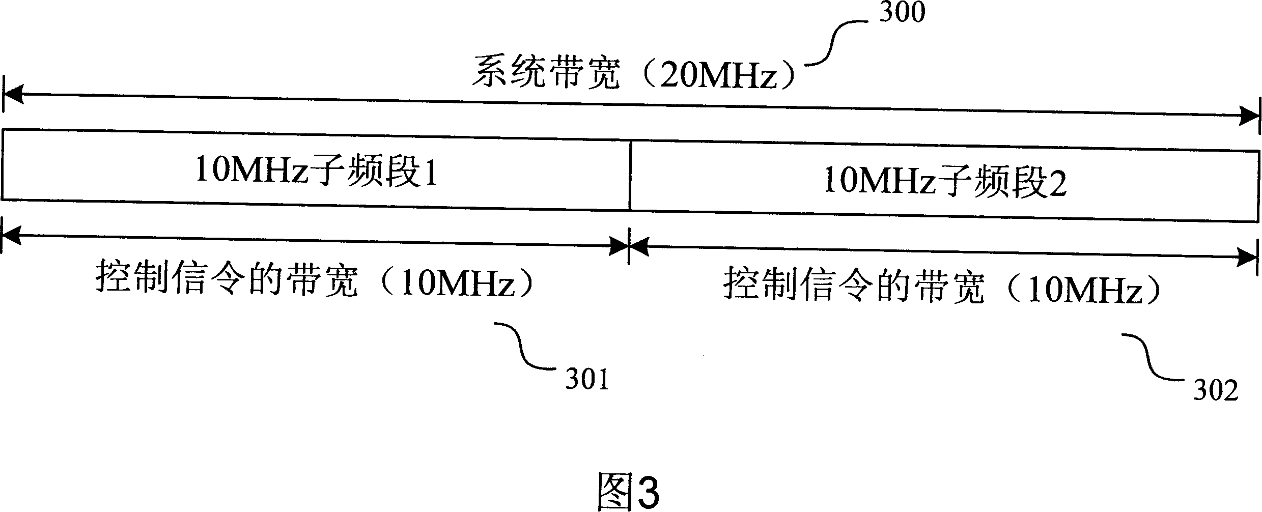
[0099] This part gives three embodiments of the invention, where it is assumed that the system bandwidth is 20MHz, and there are two user equipments with bandwidth capabilities of 10MHz and 20MHz in the system. In order to avoid making the description of this patent too lengthy, detailed descriptions of known functions or devices are omitted in the following descriptions.

no. 1 example

[0101] This embodiment is an example of the present invention for allocating downlink channel resources. The system configures two types of L1 / L2 control channels. The first type of L1 / L2 control channel is used when the resource blocks allocated by the network to user equipment are distributed to a 10MHz subband in the 20MHz system bandwidth; the second type The L1 / L2 control channel is used when the resource blocks allocated by the network to users are distributed to the entire 20MHz system bandwidth.

[0102] According to the current discussion results in LTE, each resource block contains 12 subcarriers, but when allocating resources, two resource blocks can be divided into one group, so as to allocate channel resources with 24 subcarriers as the allocation granularity, as shown in Figure 6 It is a structural diagram of 24 sub-carriers as resource allocation units within the 20MHz system bandwidth. At the same time, Table 1 lists the number of resource allocation units with...

Embodiment 1

[0114] The description about the number of resource allocation units in Embodiment 1 is also applicable to this embodiment, that is, the 10MHz bandwidth is divided into 25 resource allocation units, and the 20MHz bandwidth is divided into 50 resource allocation units.

[0115] In order to keep the single-carrier nature of the SCFDMA signal, the uplink localized transmission channel can only occupy several adjacent resource units. Like this, the number of possible localized channels in the 10MHz bandwidth is (25+1) 25 / 2= 325, the number of possible localized channels within the 20MHz bandwidth is (50+1)·50 / 2=1275. Therefore, the number of channel allocation modes that need to be indicated for the first type of L1 / L2 control channel is 325, that is, it needs bits; the number of channel allocation modes that the second type of L1 / L2 control channel needs to indicate is 1275-325×2=625, that is, it needs bits. In this embodiment, a method similar to that in Embodiment 1 may be ...


PUM


Abstract

A method for generating a control signaling by network comprises the following steps: the network collocates a first type L1 / L2 control channel and a second type L1 / L2 control channel; the network collocates user equipment with small bandwidth ability to detect the first type L1 / L2 control channel, and collocates user equipment with big bandwidth ability to detect the second type L1 / L2 control channel; the network distributes resource blocks to each user equipment, and obtains the control bit of the indication resource block information and other L1 / L2 control information; the network sends control signaling of the user equipment with small bandwidth ability on the first type L1 / L2 channel, and selects one type of L1 / L2 channel to send control signaling according to the frequency band distributed by the resource block of user equipment with big bandwidth ability. Using the method of the present invention, the L1 / L2 control signaling of the user equipment sent by network is sent in one L1 / L2 channel only, and reduces the bit spending of the L1 / L2 control signaling.

Description

technical field [0001] The present invention relates to a wireless communication system, more specifically, to a device and method for transmitting control signaling in a variable bandwidth wireless communication system. Background technique [0002] Now, the 3GPP standardization organization has begun to carry out long-term evolution (LTE, Long Term Evolution) of its existing system specifications. Among the many physical layer transmission technologies, the downlink transmission technology based on Orthogonal Frequency Division Multiplexing (OFDM, Orthogonal Frequency Division Multiplexing) and the uplink transmission technology based on Single Carrier Frequency Division Multiple Access (SCFDMA, Single Carrier Frequency Division Multiple Addressing) Technology is a hot topic of research. OFDM technology is essentially a multi-carrier modulation communication technology. Its basic principle is to decompose a high-rate data stream into several low-rate data streams and tran...

Claims


Application Information

Patent Timeline
IPC IPC(8): H04Q7/38H04B7/26H04W28/12H04W72/04H04W72/14
Inventor 李迎阳张玉建李小强李周镐
Owner BEIJING SAMSUNG TELECOM R&D CENT
Why Eureka
Try Eureka