A calibrated microelectromechanical microphone

一种话筒、话筒组件的技术,应用在电气元件、换能器电路、半导体静电换能器等方向,能够解决性能参数影响、成本低、很难消除影响等问题,达到紧凑配置、增加生产产量的效果

Inactive Publication Date: 2008-04-02
TDK CORPARATION
View PDF8 Cites 35 Cited by
  • Summary
  • Abstract
  • Description
  • Claims
  • Application Information

AI Technical Summary

Problems solved by technology

However, there is some impact on performance parameters such as amplifier gain and impedance
This effect is difficult to remove in loud, low-cost MEMS microphones where low-complexity amplifier topologies are critical to keep die-area costs low

Method used


Image

  • A calibrated microelectromechanical microphone
  • A calibrated microelectromechanical microphone

Examples


Embodiment Construction

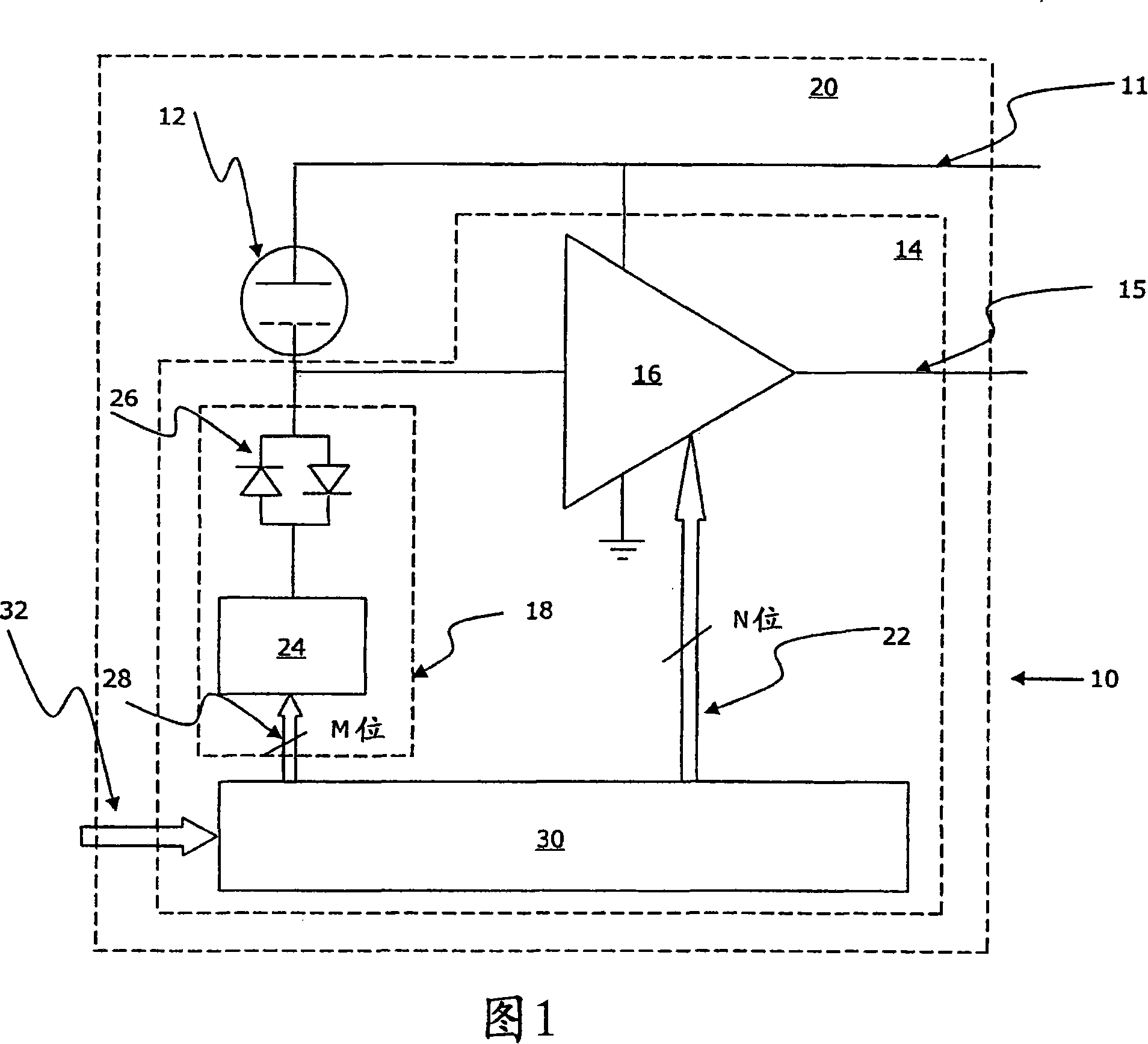
[0086] A microphone 10 according to a preferred embodiment of the present invention comprises a MEMS condenser microphone 12 and an integrated circuit portion 14 which includes a microphone (pre)amplifier 16, a DC bias generator 18, and is built into a microphone housing / package 20 middle.

[0087] Furthermore, the microphone has a voltage source 11 and an output 15 .

[0088] The amplifier 16 includes a data input 22 for adjusting its gain, the bias voltage generator 18 includes a diode arrangement 26 and a DickSon pump 24 with a data input 28 for adjusting the voltage output of the generator 18 (for a detailed description see e.g. EP -A-1599067). The Dickson pump operates by converting the M-bit information directly into a voltage.

[0089] The gain of microphone pre-amplifier 16 is adjusted by using calibration data 22 loaded into and stored in non-volatile memory 30 of integrated circuit 14 during an initial testing step in the MEMS condenser microphone 10 manufacturing ...


PUM


Abstract

The invention relates to a calibrated microelectromechanical microphone. A MEMS microphone comprising a MEMS transducer having a back plate and a diaphragm as well as controllable bias voltage generator providing a DC bias voltage between the back plate and the diaphragm. The microphone also has an amplifier with a controllable gain, and a memory for storing information for determining a bias voltage to be provided by the bias voltage generator and the gain of the amplifier.

Description

technical field [0001] The present invention relates to calibrating microphones and in particular to microcomputer-based telephone microphones comprising a memory with calibration data for setting the electrical parameters of the microphone. Background technique [0002] During normal operation, microelectromechanical ("MEMS") microphones are typically provided with a fixed DC bias between the diaphragm and the chassis structure. In EP 1599607A2 a specific operation of a DC bias for removing or reducing the electrostatic attraction between the diaphragm and the chassis is proposed and disclosed under microphone default conditions in combination with so-called diaphragm collapse. [0003] US 2006 / 062406 A1 discloses a condenser microphone comprising a programmable DC bias for the microphone's condenser transducer and a memory for storing the DC bias setting. WO 01 / 78446A1 discloses an electret microphone comprising a variable sensitivity / variable gain circuit connected betwe...

Claims


Application Information

Patent Timeline
Patent Type & Authority Applications(China)
IPC IPC(8): H04R29/00H04R3/00
CPCH04R19/04H04R29/004H04R19/005
Inventor 卡斯坦·法莱森延斯·K.·波尔森拉斯·J.·斯坦博格约泽夫·J.·G.·博世
Owner TDK CORPARATION
Why Eureka
Try Eureka