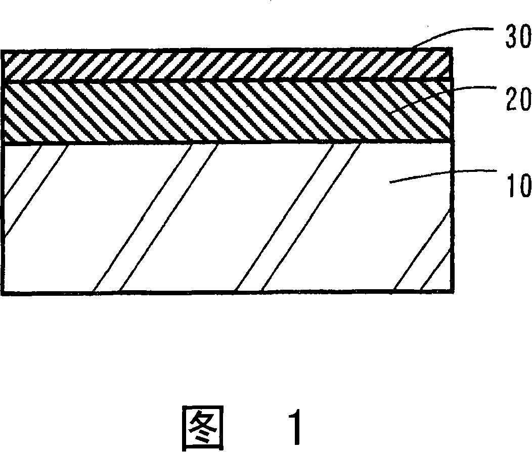
Infrared shielding layer-coated glass plate and process for its production
A manufacturing method and barrier layer technology, applied in the direction of chemical instruments and methods, glass/slag layered products, coatings, etc., can solve the problems of low chemical resistance, achieve high radio wave permeability, simplify manufacturing methods, mechanical Excellent durability and chemical resistance
- Summary
- Abstract
- Description
- Claims
- Application Information
AI Technical Summary
Problems solved by technology
Method used
Image
Examples
Embodiment
[0070] Hereinafter, examples of the present invention will be given for further description, but the present invention is not limited to these examples.
[0071] In addition, the average particle diameter of the ITO fine particles in the obtained infrared blocking layer was estimated by observation with a transmission electron microscope (TEM). In addition, the obtained glass plate with an infrared blocking layer was evaluated as follows.
[0072] [evaluate]
[0073] (1) Layer thickness: The cross-section of the fired infrared blocking layer was observed with a scanning electron microscope (manufactured by Hitachi: S-800), and the layer thickness of the first layer and the layer of the second layer were obtained from the obtained observation image. Thick [μm].
[0074] (2) In-layer composition: X-ray photoelectron spectroscopy (XPS) was used to measure the composition distribution (mass ratio in terms of oxides) of the infrared blocking layer after firing for In, Si, and Ti ...
example 1
[0082]Use a bead mill to disperse ITO microparticles with an average primary particle size of 45nm, a powder color of (x, y)=(0.353, 0.374) in the xy chromaticity coordinates of the c light source, and a 2° field of view, in a powder containing 0.02% by mass. The ITO microparticle dispersion liquid A containing 20 mass % of ITO was produced in the ethanol / 1-propanol mixed (volume ratio=50 / 50) solvent of concentrated nitric acid. The number-plane dispersion particle diameter of the ITO fine particles in the dispersion liquid A was measured using a laser zeta potential meter (manufactured by Otsuka Electronics Co., Ltd., ELS-8000), and it was 80 nm.
[0083] 2-Butanol was added to the said dispersion liquid A, and the dispersion liquid diluted so that the solid content concentration might become 7 mass % was made into the dispersion liquid B.
[0084] The resulting dispersion B was coated on a 3.5 mm thick ultraviolet-absorbing green glass plate (Tv: 75%, Te: 47%, T1 = 22%, T2 =...
example 2
[0089] Further, 2.2 g of diisopropoxybis(acetylacetonate)titanium diisopropoxide (manufactured by Mitsubishi Gas Chemical Co., Ltd., trade name: TAA) was mixed with 100 g of the dispersion B, and stirred for 1 hour to obtain a dispersion C. In the production of the lower layer, a glass plate with an infrared blocking layer was produced in the same manner as in Example 1, except that the above-mentioned dispersion liquid C was used instead of the dispersion liquid B. Table 1 and Table 2 show the property evaluation results of the obtained glass plate with an infrared blocking layer.
PUM
| Property | Measurement | Unit |
|---|---|---|
| thickness | aaaaa | aaaaa |
| thickness | aaaaa | aaaaa |
| particle diameter | aaaaa | aaaaa |
Abstract
Description
Claims
Application Information
 - R&D
- Intellectual Property
- Life Sciences
- Materials
- Tech Scout
- Unparalleled Data Quality
- Higher Quality Content
- 60% Fewer Hallucinations
Browse by: Latest US Patents, China's latest patents, Technical Efficacy Thesaurus, Application Domain, Technology Topic, Popular Technical Reports.
© 2025 PatSnap. All rights reserved.Legal|Privacy policy|Modern Slavery Act Transparency Statement|Sitemap|About US| Contact US: help@patsnap.com

