Improved electrophoretic display and preparation method thereof

An electrophoretic display and electrophoretic technology, applied in the direction of instruments, identification devices, nonlinear optics, etc., can solve the problems of application limitations, unfavorable display energy saving, etc., and achieve the effects of improving reflectivity, optical stability, and contrast

Inactive Publication Date: 2008-04-09
BEIJING PAIRUIGEN SCI & TECH DEV
View PDF18 Cites 17 Cited by
  • Summary
  • Abstract
  • Description
  • Claims
  • Application Information

AI Technical Summary

Problems solved by technology

Because if the maintenance time is too short, the scanning voltage needs to be continuously applied to the electrodes to refresh the display content, which is not conducive to the energy saving of the display.
Especially in the application of e-paper, e-book, etc. is restricted

Method used


Image

  • Improved electrophoretic display and preparation method thereof
  • Improved electrophoretic display and preparation method thereof
  • Improved electrophoretic display and preparation method thereof

Examples


Embodiment Construction

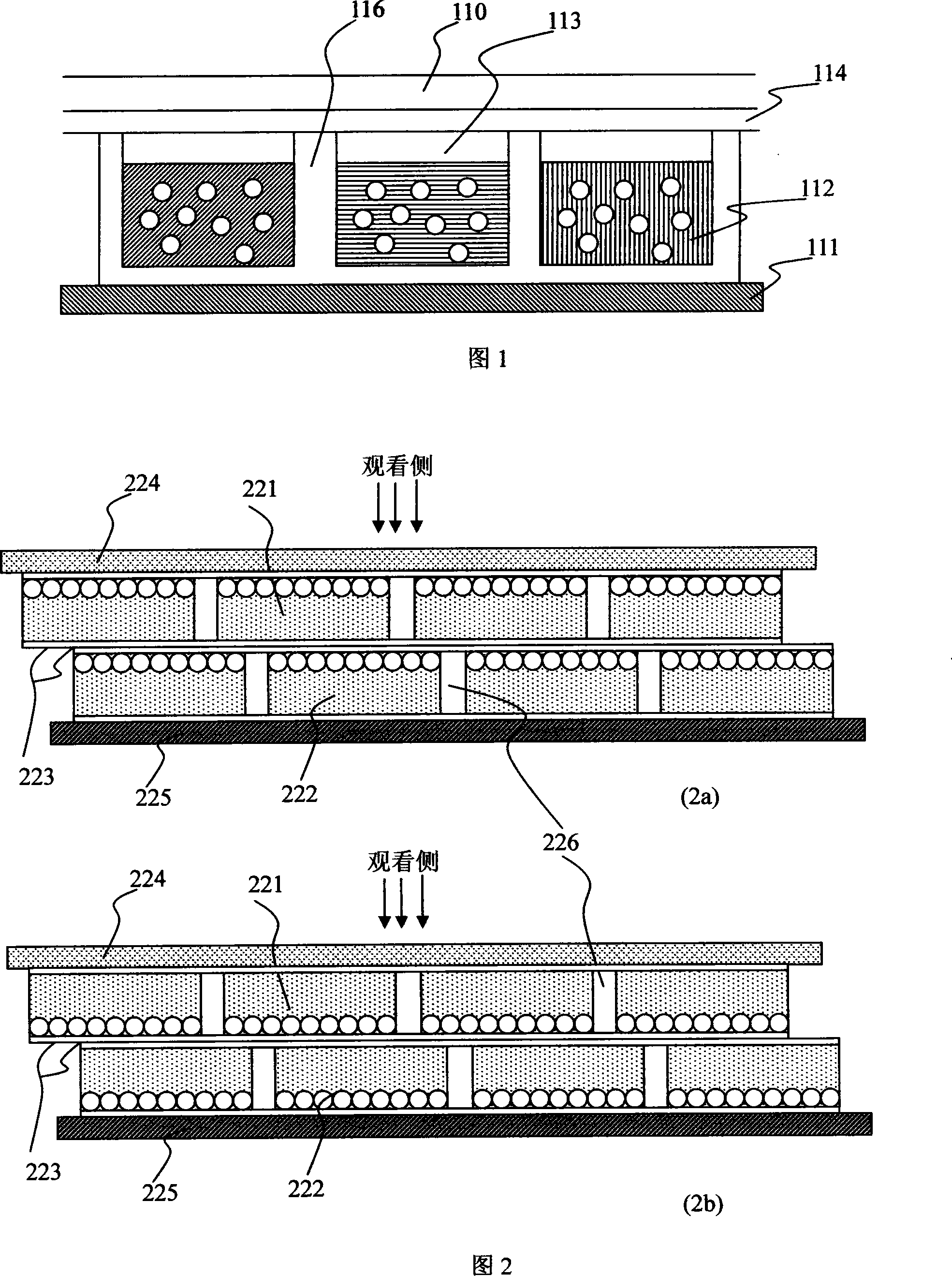
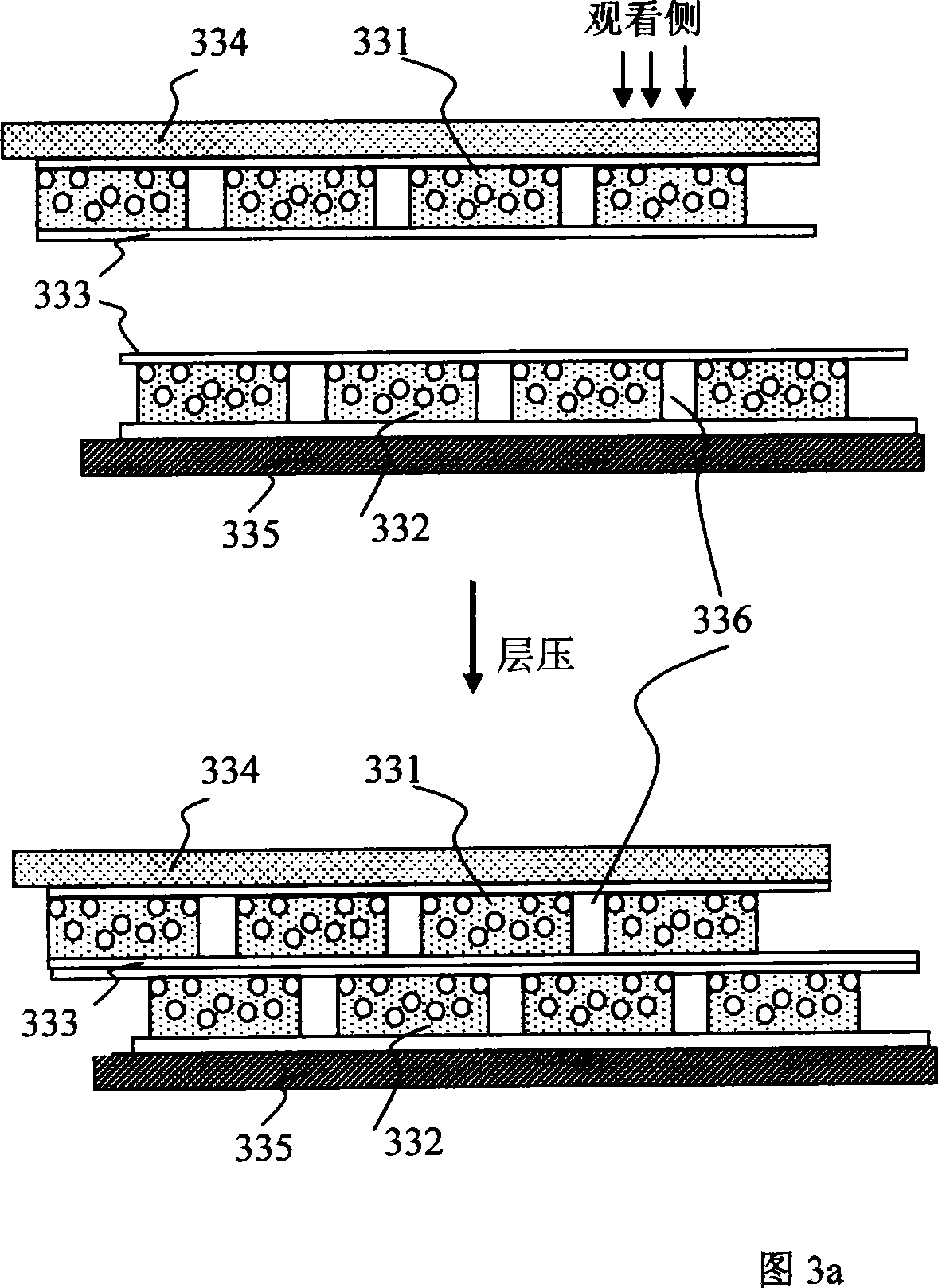
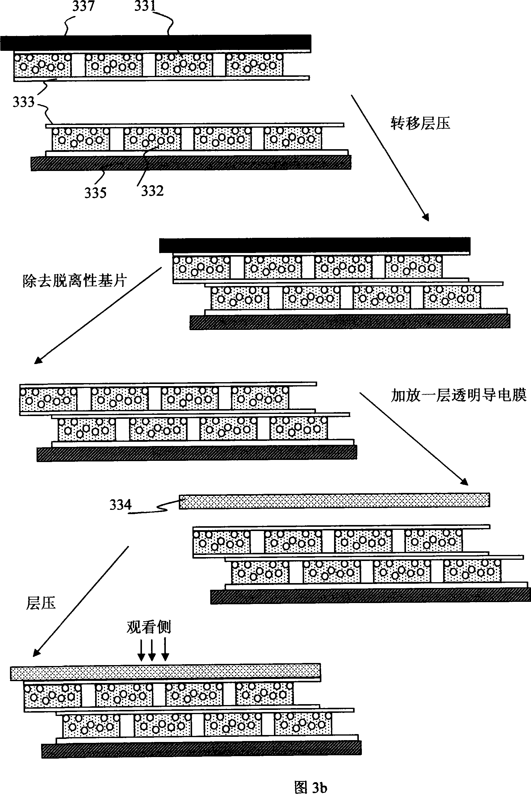
[0070] Terminology Explanation:

[0071] "Microcup": means a cup-shaped recess produced by micromolding or pattern exposure, having a well-defined shape, size and aspect ratio predetermined according to the specific parameters of a certain manufacturing method.

[0072] "Aspect ratio" is a general term in the field of electrophoretic displays and, for microcups, refers to the ratio of depth to width or depth to length of a cell.

[0073] "Maximum optical density (Dmax)" means the maximum optical density a display can achieve.

[0074] "Minimum optical density (Dmin)" refers to the minimum optical density at which the background appears.

[0075] "Contrast ratio" is defined as the ratio of the percent reflectance of an electrophoretic display in the state of minimum optical density to the percent reflectance of the display in the state of maximum optical density.

[0076] "Display element": the basic unit with optical switching performance, such as display boxes using microcu...


PUM


Abstract

The invention relates to an improved electrophoretic display and a manufacturing method, two transparent electrophoretic layers with special electrical performance are added to the display elements to form the electrophoretic display, which can achieve rapid display state switch and better display stability and long display maintain capability, particularly after multi-layers of electrophoretic display elements are superposed, two additional transparent electrophoretic layers with special electrical performance can not only achieve rapid display state switch and better display stability and long display maintain capability, but also has the performances of improving contrast, switching performance, the reflectivity and structure integrality in the minimum optical density state. At the same time the invention also provides the electrophoretic display manufacturing method.

Description

technical field [0001] The present invention relates to electrophoretic displays capable of improved contrast, switching performance, display stability, reflectivity at minimum optical density state, and structural integrity, and to methods of making the same. Background technique [0002] Electrophoretic displays are non-emissive devices based on the electrophoresis of charged pigment particles suspended in a solvent, first proposed in 1969. Such displays generally comprise two plates with electrodes placed opposite each other with a plastic spacer. Usually, one of the electrode plates is transparent, and between the two electrode plates, the suspension is sealed. The suspension contains pigmented solvent and particles of charged pigment. When a voltage difference is applied between the two electrodes, the pigment particles will migrate to one side, whereupon the color of the pigment or the color of the solvent can be seen depending on the polarity of the voltage differen...

Claims


Application Information

Patent Timeline
Patent Type & Authority Applications(China)
IPC IPC(8): G02F1/167G09F9/37
Inventor 须清
Owner BEIJING PAIRUIGEN SCI & TECH DEV
Why Eureka
Try Eureka