
Liquid-cooled battery and method for operating such a battery

A battery, liquid cooling technology, applied in secondary batteries, battery pack components, secondary battery gas removal, etc., can solve the problem of fire, explosive gas entering the battery, etc., and achieve the effect of high safety and compact structure

Inactive Publication Date: 2008-04-09
DAIMLER AG
View PDF3 Cites 9 Cited by
  • Summary
  • Abstract
  • Description
  • Claims
  • Application Information

AI Technical Summary

Problems solved by technology

This has the disadvantage that hot and potentially explosive gases enter the area surrounding the battery, which can lead to hazards such as fire

Method used


Image

  • Liquid-cooled battery and method for operating such a battery
  • Liquid-cooled battery and method for operating such a battery
  • Liquid-cooled battery and method for operating such a battery

Examples


Embodiment Construction

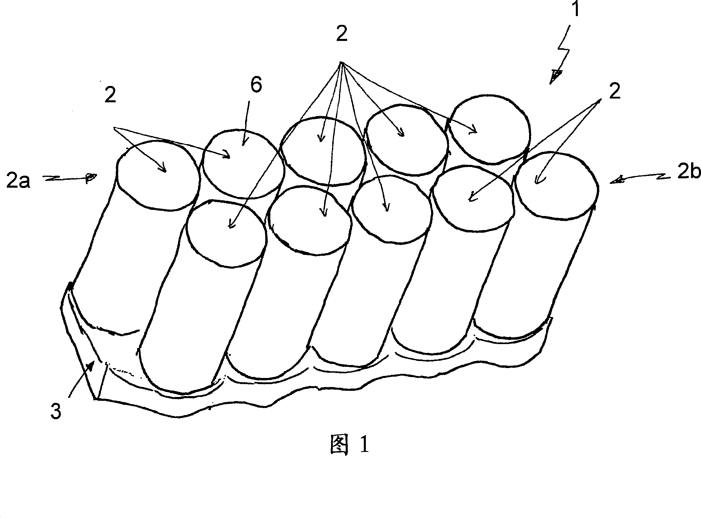
[0021] FIG. 1 schematically shows a battery 1 . The battery 1 comprises a plurality of individual energy storage cells 2 which are arranged next to each other in rows, shown by way of example in FIG. 1 as two rows 2a, 2b. The two rows 2a, 2b shown in Fig. 1 are arranged alternately so that the adjacent rows 2a, 2b are staggered relative to each other by half of the distance between the centerlines of the energy storage units 2 in a row. This allows the rows 2a, 2b to be packed very closely relative to each other. Overall, this results in a very compact construction of the battery 1 .

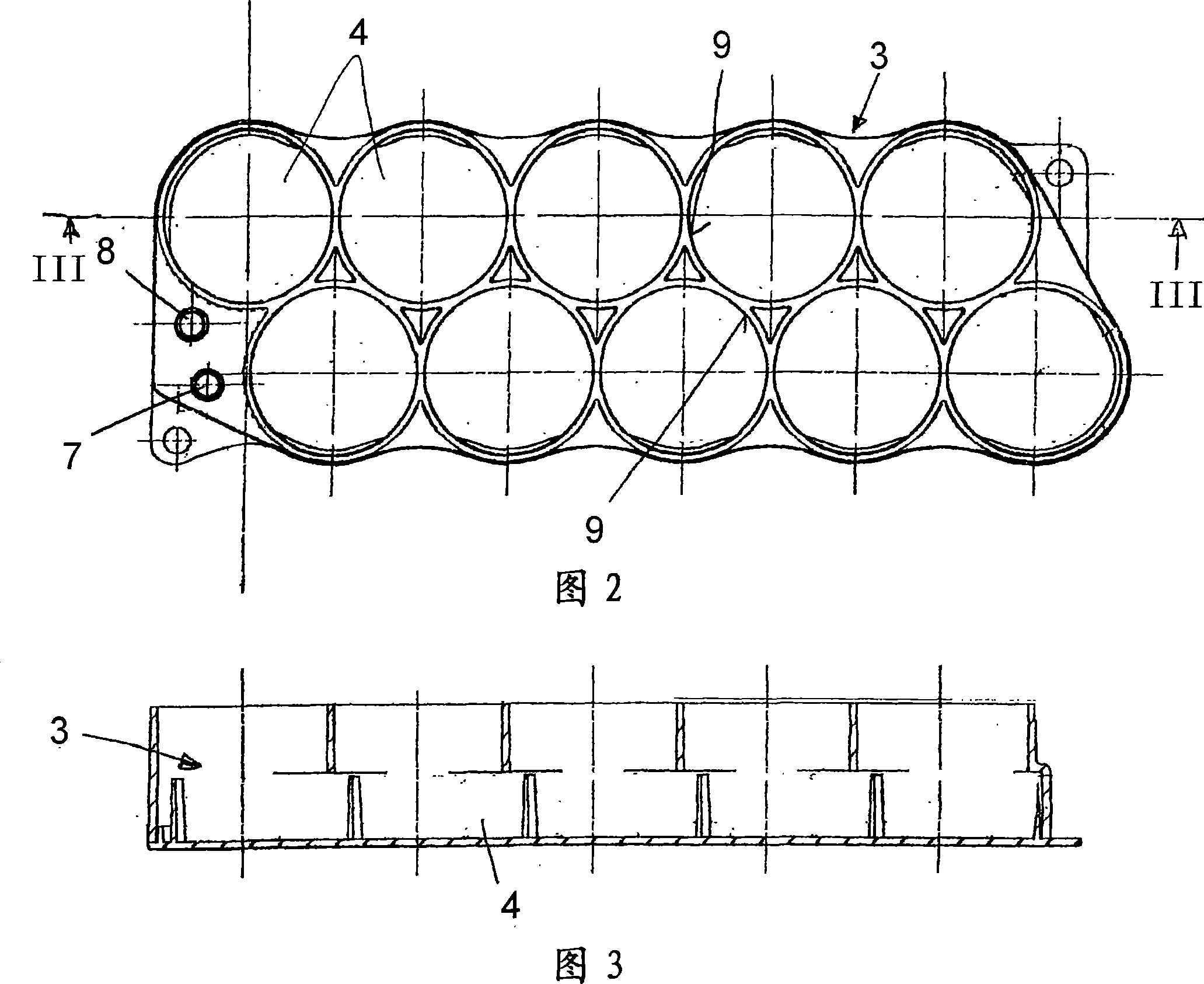
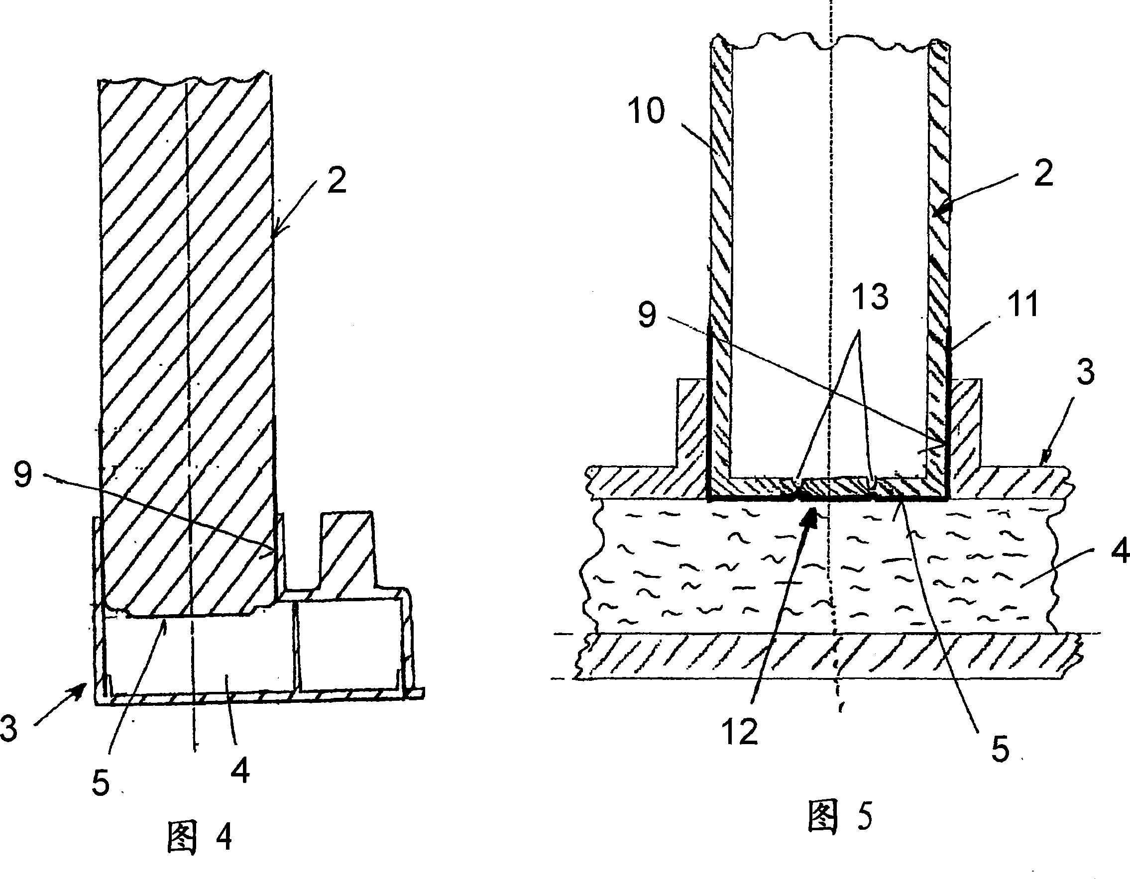
[0022] In addition, the battery is cooled by means of a cooler 3 having an internal space 4 (not shown in FIG. 1 ) through which a cooling medium can flow, through which the cooling medium flows during normal use. Each energy storage unit 2 is in thermal contact with the cooler 3 at its respective end faces 5 (not shown in FIG. 1 ). Said end face forming the bottom 5 of the energy storage uni...


PUM

PropertyMeasurementUnit
thicknessaaaaaaaaaa

Abstract

A liquid-cooled battery, in particular in the form of an energy store for an electrical drive in a motor vehicle is provided. The battery has a plurality of storage cells 2 and at least one volume 4 which makes thermally conductive contact with the storage cells 2 and through which a cooling medium can flow. Each of the storage cells 2 has a safety valve 12 which opens the storage cell when a predetermined media pressure in it is exceeded, and connects the volume of the storage cell to the surrounding area. The safety valve 12 is arranged in the storage cell 2 and the storage cell 2 is arranged with respect to the volume 4 through which the cooling medium can flow such that a connection is produced between the volume 4 through which the cooling medium can flow, and the interior of the storage cell 2 if the safety valve 2 is operated.

Description

technical field [0001] The invention relates to a liquid-cooled battery of the type defined in detail in the preamble of claim 1 and to a method of operating a liquid-cooled battery as defined in detail in the preamble of claim 14 . Background technique [0002] A battery is known from JP 2004 178 909 A in which the individual cells each have a safety valve. When the internal pressure of the individual battery cells becomes too high, the safety valve opens, so that the gases escaping from the individual energy storage cells (Speicherzelle, battery cells) are discharged into the surroundings. This has the disadvantage that hot and possibly explosive gases enter the area surrounding the battery, which can lead to hazards such as fires. [0003] Furthermore, from JP 10 241 739 A an energy storage unit of a cooled battery is known, which likewise has a safety valve which opens above a known temperature threshold value and a cooling module. The cooling module itself also has a ...

Claims


Application Information

Patent Timeline
Patent Type & Authority Applications(China)
IPC IPC(8): H01M10/52H01M2/12
CPCY02E60/12H01M2/1241H01M10/5075H01M10/5057H01M10/5004H01M10/5016H01M10/503H01M10/52H01M10/504H01M10/613H01M10/625H01M10/643H01M10/653H01M10/6556H01M10/6567H01M50/3425Y02E60/10
Inventor O·比切M·布陵W·杜尔W·施怀恩巴赫T·索齐卡-古特L·怀恩申克尔
Owner DAIMLER AG
Learn More