Method for shaping plastics material

A plastic material and plastic technology, applied in applications, home appliances, and other home appliances, can solve the problems of low thermal efficiency of infrared panel heaters and longer heating time of plastic materials, and achieve the effect of improving heating efficiency and improving heating efficiency

Inactive Publication Date: 2008-04-16
FUJIFILM CORP
View PDF1 Cites 7 Cited by
  • Summary
  • Abstract
  • Description
  • Claims
  • Application Information

AI Technical Summary

Benefits of technology

The inventive process described for improving the heat transfer during melting processes involves utilizing CO2/laser devices with special features like low power consumption (LP) mode and use of specific types of polymers called carbonsiloxanes. These modifications improve the effectiveness of these techniques while also reducing their negative impact upon other properties such as strength and durability of resulting product components.

Problems solved by technology

The technical problem addressed in this patented technology relates how to improve the efficient use of energy during the process for producing plastic optical components through thermally induced expansion caused by pressure moldings.

Method used


Image

  • Method for shaping plastics material
  • Method for shaping plastics material
  • Method for shaping plastics material

Examples


Embodiment Construction

[0043] Next, embodiments of the present invention are described in detail by referring to the drawings.

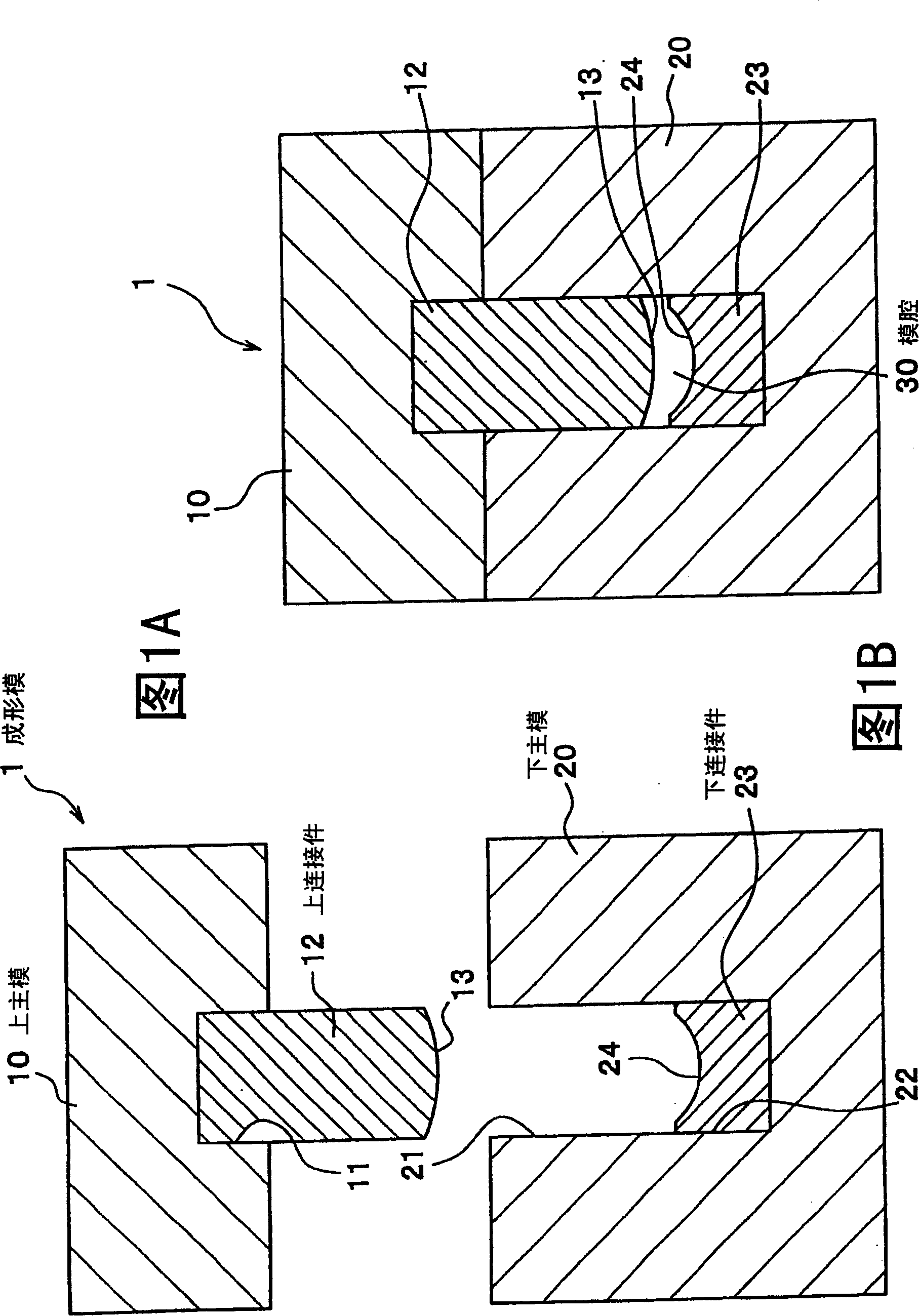
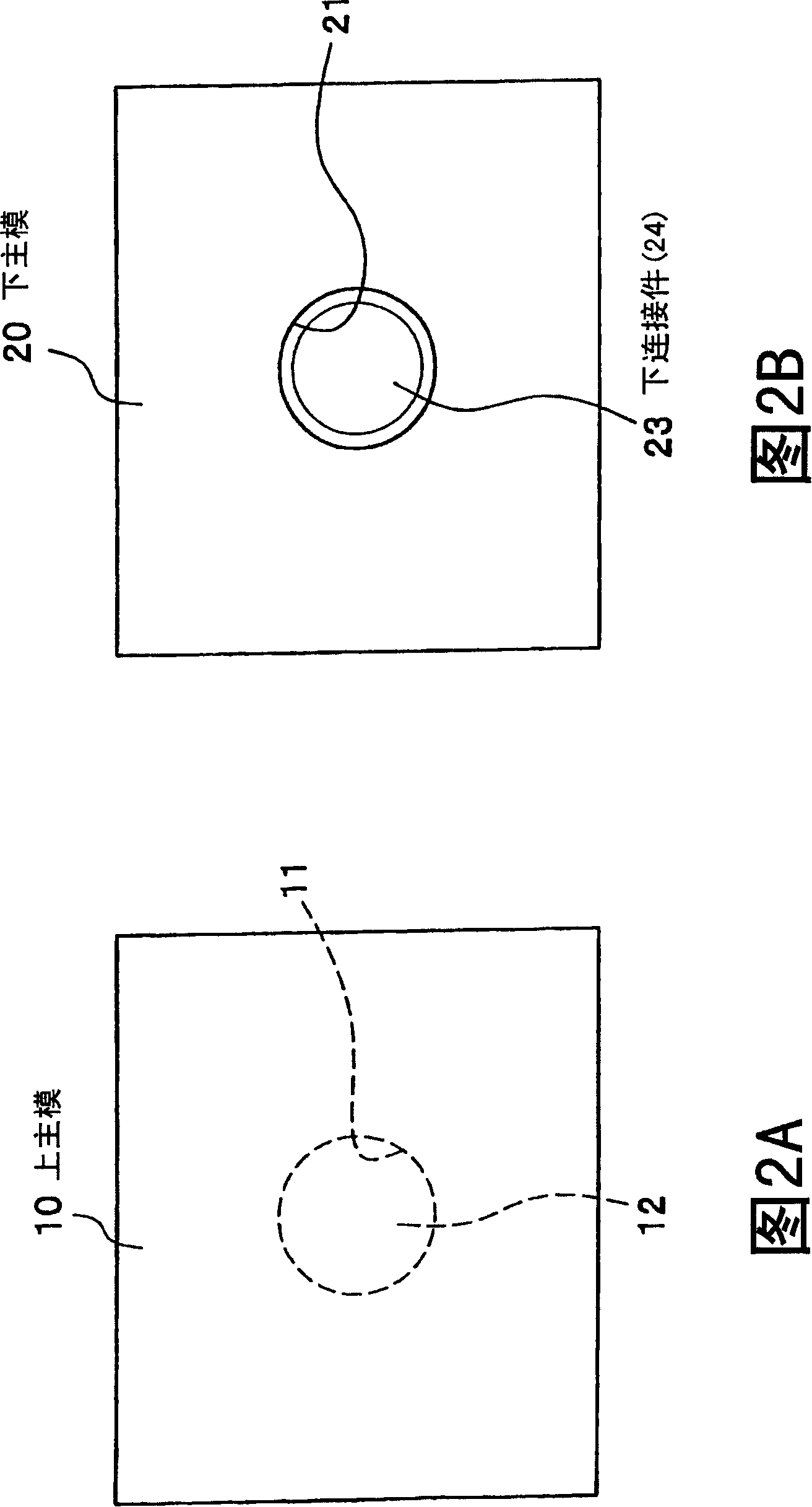
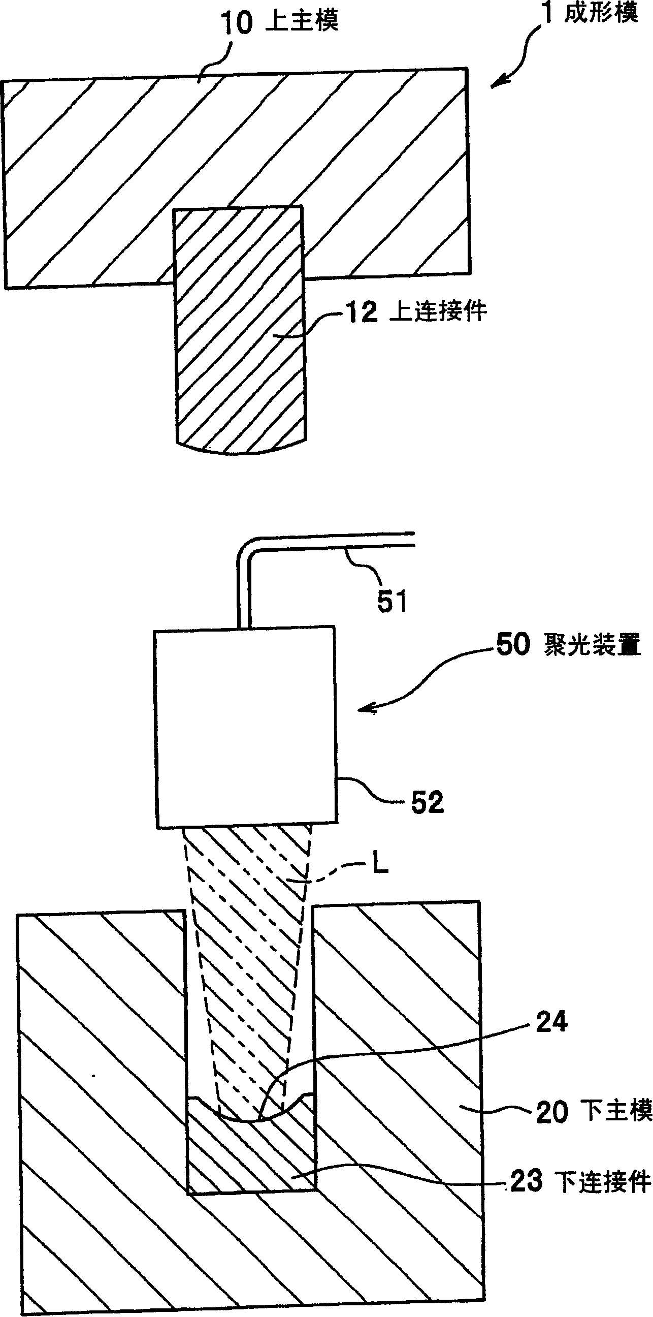
[0044]1A and 1B are views showing a forming die used in the forming method of the plastic material of the present embodiment. FIG. 1A is a side sectional view showing separate main forms, and FIG. 1B is a side sectional view showing the main forms joined together. 2A and 2B show views of a forming die used in the forming method of the plastic material of the present embodiment. FIG. 2A is a plan view showing an upper main mold, and FIG. 2B is a plan view showing a lower main mold. image 3 is a side sectional view showing a molding die used in the molding method of the plastic material of this embodiment, in which light concentrating means are provided between main dies.

[0045] In this embodiment, an example of a method for manufacturing a plastic lens using compression molding of a plastic material will be used to explain the present invention.

[0046] (Structure of ...


PUM

PropertyMeasurementUnit
Diameteraaaaaaaaaa

Abstract

A plastics shaping method, comprises: plastic material in die module being radiated using infrared laser or focusing infrared ray to heat the plastic material and press the said plastic material, in order that the plastic material is distorted into given shape. The said plastic material is permeable visible transparent material added with infrared absorbing material. The infrared laser is radiated using a carbon dioxide gas laser device. The water content of the plastic material is not more than 0.01% by weight. The infrared ray is radiated on the plastic material under the inert atmosphere. The plastic material is selected from any one of polycarbonate, polyester, cyclopolyolefine, acrylic resin, alicyclic ring acrylic resin and olefin-maleimide alternating copolymer. Thus, the plastic material is effectively heated by infrared ray in short time to increase the production efficiency of the product.

Description


Claims


Application Information

Patent Timeline
Owner FUJIFILM CORP
Why Eureka
Try Eureka