Bare engine module

An optical-mechanical module and planar technology, applied in optics, instruments, projection devices, etc.

Inactive Publication Date: 2008-04-16
BENQ CORP
View PDF0 Cites 0 Cited by
  • Summary
  • Abstract
  • Description
  • Claims
  • Application Information

AI Technical Summary

Problems solved by technology

Designed to resolve imaging issues caused by cumulative tolerances of optomechanical housings, projection lenses, and digital micromirror elements

Method used


Image

  • Bare engine module
  • Bare engine module
  • Bare engine module

Examples


Embodiment Construction

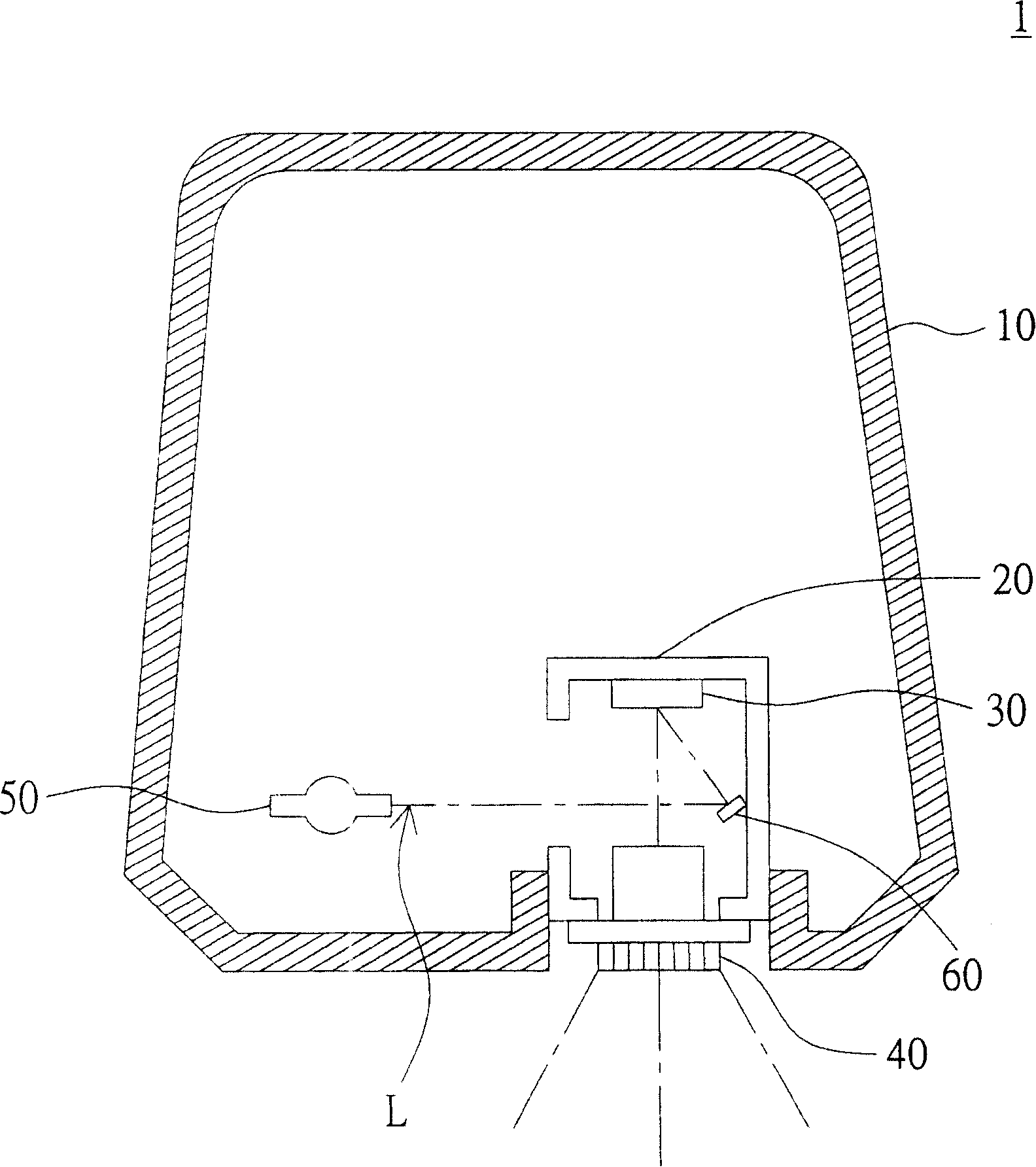
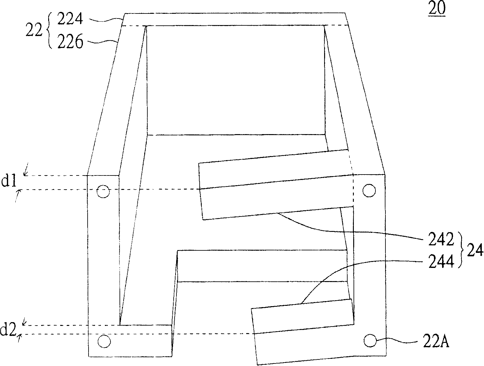
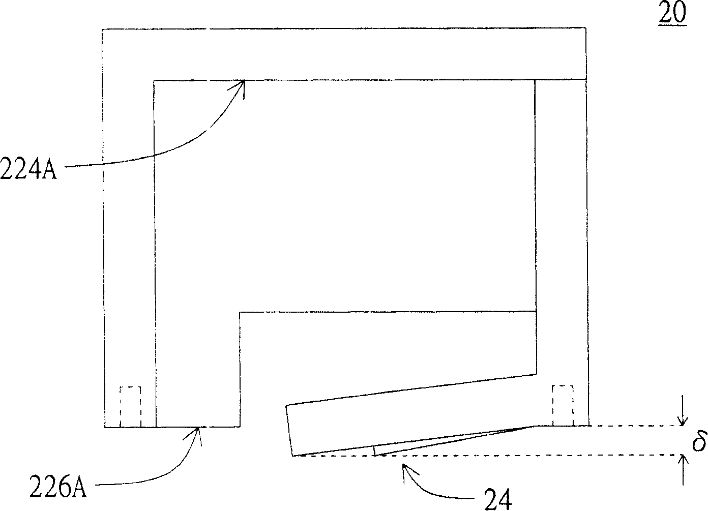
[0050] Please refer to figure 1 , which shows a schematic diagram of a projection device according to a preferred embodiment of the present invention. Such as figure 1 As shown, the projection device 1 includes a housing 10 , a support structure 20 , a first module 30 , and a second module 40 . The bulb 50 and the reflector 60. The supporting structure 20 , the first module 30 , the second module 40 , and the reflector 60 are the optical-mechanical modules of the projection device 1 . The supporting structure 20 and the bulb 50 are respectively disposed inside the casing 10 , and the first module 30 , the second module 40 and the reflector 60 are respectively disposed in the supporting structure 20 . Wherein, the light bulb 50 is used to generate the light L to pass through the reflective lens 60 and pass through the first module 30 and the second module 40 in sequence to send the image out from the projection device 1 .

[0051] The first module 30 , such as a digital mic...


PUM


Abstract

The invention discloses an optical machine module comprising a supporting structure, a first module and a second module. The supporting structure comprises a body part and an adjustment part, wherein, the body part has a first plane and a second plane which are opposite to each other, and the adjustment part comprises a first flexible element and a second flexible element which are respectively arranged on the body part and bulge out of the second plane. The first module is arranged on the first plane, and the second plane is arranged on the second plane and abuts against the first flexible element and the second flexible element, wherein, the arrangement plane of the second module is adjusted by adjusting the adjustment part, thereby adjusting the depth of parallelism of the first module and the second module.

Description

technical field [0001] The invention relates to an optical-mechanical module and an assembly method thereof, in particular to an optical-mechanical module capable of adjusting the parallelism of a projection lens and a digital micromirror element and an assembly method thereof. Background technique [0002] A digital light processing (DLP) projector mainly includes a projection lens, a light engine, a digital micro-mirror device (DMD) and a light bulb. The light bulb is used to project light onto the digital micromirror element of the light engine, and then project the image through the projection lens. [0003] Since the digital optical processing projector produces images through the projection lens, the digital micromirror element is one thing for the projection lens. Therefore, when the distance between the DMD and the projection lens changes, the imaging distance also changes accordingly. Since the digital micromirror element is composed of many mirror elements, each ...

Claims


Application Information

Patent Timeline
IPC IPC(8): G03B21/14
Inventor 郭建峰
Owner BENQ CORP
Why Eureka
Try Eureka