A snapping and aligning device for large-format steel plates

A technology of snapping device and large format, which is applied in auxiliary devices, plasma welding equipment, laser welding equipment, etc., can solve the problems of large deformation of thin steel plates, no adjustment, and high mechanical properties, and achieves simple and practical device structure and convenient main coordination. The effect of fine-tuning and reducing the processing cost

Active Publication Date: 2017-07-28
BAOSHAN IRON & STEEL CO LTD
View PDF9 Cites 1 Cited by
  • Summary
  • Abstract
  • Description
  • Claims
  • Application Information

AI Technical Summary

Problems solved by technology

The deformation of the thin steel plate is large, and the ordinary positioning block cannot meet the high requirements of reducing the small deformation of the steel plate by laser or plasma cutting
The commonly used steel plate positioning has no adjustment function. For the positioning device installed on the non-fixed frame, it is necessary to compensate the parallelism error between the cutting machine and the base from the control level of the cutting system. If the non-fixed frame is replaced, the error value will be reduced. It needs to be reset from the system level, which affects the stability of the system, and has higher requirements for mechanical performance
[0003] Chinese Patent No. CN102601641A discloses a steel plate positioning mechanism. The technical solution is to adjust the positioning position of the steel plate by using sleeves with different diameters in the outer ring of the positioning block. This method has technical difficulties for cutting operations that require precise adjustment of positioning. Guarantee the positioning accuracy requirements for large-format steel plates, and have a great impact on the shape error of cut steel plates that need to be kept
[0005] Chinese patent CN201713138U discloses a sheet material alignment device. This technical solution uses sheet material limit, and the sheet material alignment position is determined by the installation position of the sheet material alignment device. It cannot adapt to the situation of sheet material changes, and the positioning accuracy satisfies Without the requirement of high-precision cutting, the steel plate is easily scratched

Method used


Image

  • A snapping and aligning device for large-format steel plates
  • A snapping and aligning device for large-format steel plates
  • A snapping and aligning device for large-format steel plates

Examples


Embodiment 3

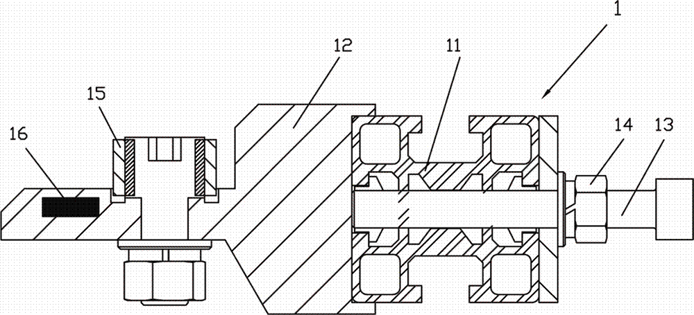
[0053] see Figure 5 , which shows the third embodiment of the positioning device of the present invention, the positioning device 1 also includes,

[0054] Two guide profiles 17, 17' are respectively arranged on one side of the positioning base 11 where the sliding groove is provided;

[0055] The positioning mounting frame 12 is arranged between the two guide profiles 17, 17', and the positioning mounting frame 12 adopts a split structure, including:

[0056] Install the slide block 122, set the positioning block 15 in the center of its upper end surface, and set the magnet 16 in the two sides;

[0057] Two installation brackets 123, 123' are arranged between the two guide profiles 17, 17', guide grooves 1231 are provided on the front side of the installation brackets 123, 123', and the inner sides of the installation brackets 123, 123' are arranged along the length direction. Step surfaces 1232, 1232' for sliding the sliding block 122; on both sides of the sliding block 1...


PUM


Abstract

A device used for neatly beating and aligning a large-width steel plate comprises at least three positioning devices. At least one positioning device is arranged on the lateral side in the width direction of the steel plate. At least two positioning devices are arranged on the lateral side in the length direction of the steel plate. Each positioning device comprises a positioning base, a positioning installation frame and at least three neatly beating devices, wherein a slide groove is formed in a side face of the base, one end of the positioning installation frame is positioned in the slide groove of the positioning base and is movably connected to the positioning base through an adjustment bolt, a positioning block is arranged at the other end of the positioning installation frame, at least one neatly beating device is arranged on the lateral side in the width direction of the steel plate, and at least two neatly beating devices are arranged on the lateral side in the length direction of the steel plate. Each neatly beating device comprises an installation machine frame, a piston cylinder, a dual-action cylinder and a neatly beating plate, wherein cylinder bodies are arranged on the installation machine frame through fixing shafts and cylinder installation blocks, the upper portion of the neatly beating plate is movably connected to a piston rod of the piston cylinder through a pin shaft, the middle of the neatly beating plate is connected to one end of the installation machine frame through a pivoting shaft, an angle lager than 90 degrees is formed by the upper portion and the lower portion of the neatly beating plate, and the neatly beating plate is driven by the piston cylinder through the piston rod to rotate around the fixing shaft in a reciprocating mode.

Description

technical field [0001] The invention relates to steel plate processing equipment, in particular to a snapping and aligning device for large-format steel plates, and is especially suitable for occasions such as laser or plasma cutting that require high cutting precision of steel plates. Background technique [0002] In the cutting process of the steel plate, since the initial position of the steel plate has a great influence on the size and shape error of the steel plate, the initial positioning of the steel plate is required. The deformation of the thin steel plate is large, and the ordinary positioning block cannot meet the high requirements of reducing the small deformation of the steel plate by laser or plasma cutting. The commonly used steel plate positioning has no adjustment function. For the positioning device installed on the non-fixed frame, it is necessary to compensate the parallelism error between the cutting machine and the base from the cutting system control l...

Claims


Application Information

Patent Timeline
Patent Type & Authority Patents(China)
IPC IPC(8): B23K37/04B23K10/00B23K26/38B23K101/18
CPCB23K10/00B23K26/38B23K37/0408B23K2101/18
Inventor 乔俊良王玉明吴瑞珉
Owner BAOSHAN IRON & STEEL CO LTD
Why Eureka
Try Eureka