
High-efficiency fluorescent converted LED light source and backlight module

A technology of LED light source and backlight module, which is applied to optical elements, optics, nonlinear optics and other directions used to change the spectral characteristics of emitted light, can solve problems such as complex process implementation, and achieve low-cost implementation and improved efficiency. Effect

Active Publication Date: 2008-04-16
APPOTRONICS CORP LTD
View PDF0 Cites 50 Cited by
  • Summary
  • Abstract
  • Description
  • Claims
  • Application Information

AI Technical Summary

Problems solved by technology

[0009] Even so, the disadvantage of the existing fluorescent conversion LED light source is that the fluorescent conversion efficiency affected by the absorption efficiency of the excitation photon and the fluorescence extraction (Extracting) efficiency still has room for further improvement.
especially figure 2 The scheme shown is more complex in terms of process implementation

Method used


Image

  • High-efficiency fluorescent converted LED light source and backlight module
  • High-efficiency fluorescent converted LED light source and backlight module
  • High-efficiency fluorescent converted LED light source and backlight module

Examples


Embodiment Construction

[0032] Below, the present invention is further described in conjunction with the preferred embodiments shown in the accompanying drawings.

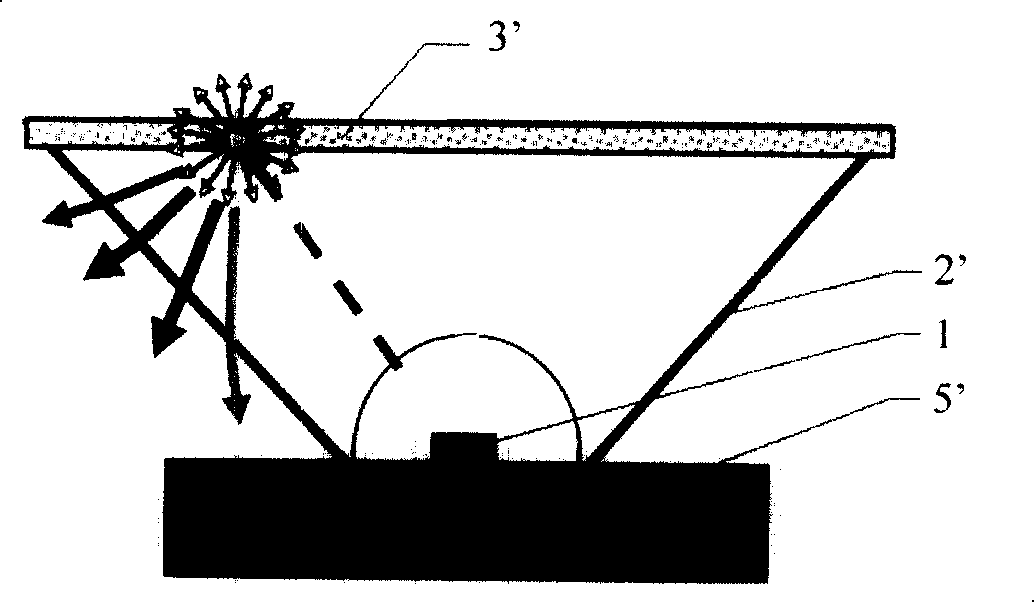
[0033] Such as Figure 4 As shown, the structure of the LED light source of the present invention includes LED 14, which is a surface-mounted light-emitting diode (including a single light-emitting diode or an array-type light-emitting diode), or a light-emitting chip formed on a substrate 15 (including a single or array-type light-emitting diode). light-emitting chip). The LED 14 is arranged at the bottom of the reflective cup 13; the reflective cup 13 can be realized by any known technology, such as figure 1 Reflective cups with specularly reflective or diffusely reflective cup walls can also be replaced by any known technique, such as figure 2 The transmissive cup 2' in it, or the collimating lens with light converging function equally (for the convenience of description, the reflective cup mentioned below, if not otherwise specified,...


PUM

PropertyMeasurementUnit
Luminous wavelengthaaaaaaaaaa

Abstract

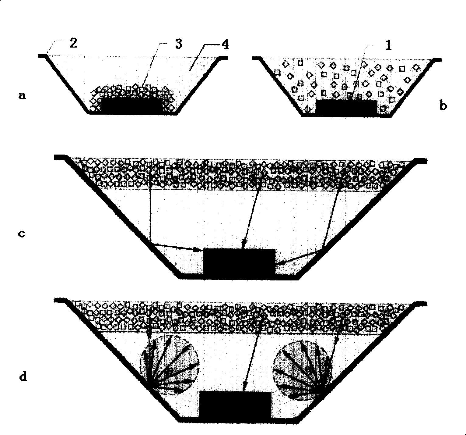
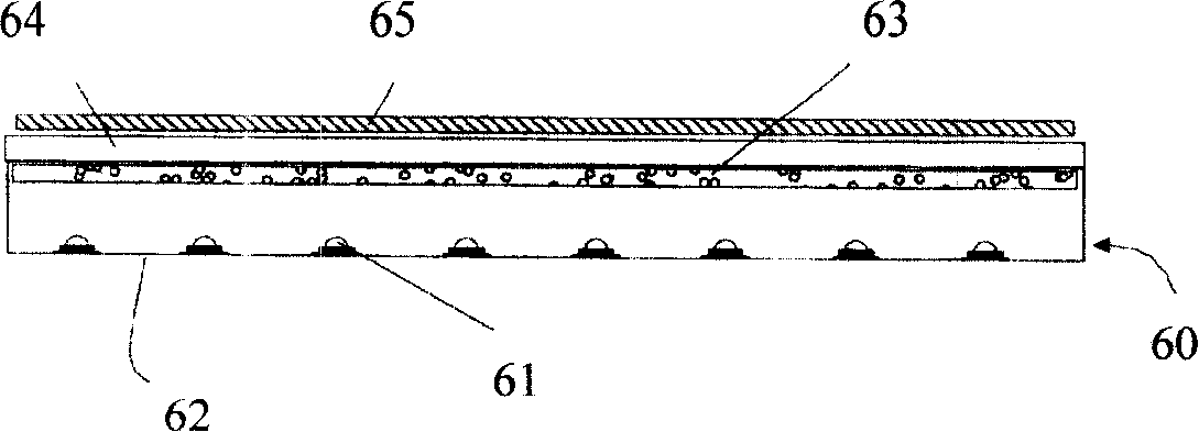
A high efficient fluorescence conversion LED light source and backlight module comprise an LED arranged in a reflecting cup or the bottom of a collimating lens, and a fluorescent powder layer with predetermined thickness which is arranged on the top and is scattered with or coated with fluorescent powders and in particular comprises a first cut-off filter which is arranged between the fluorescent powder layer and the top of the reflecting cup or the collimating lens. Photons from the predetermined wavelength range of the LED penetrate the cut-off filter with an angle of incidence smaller than the predetermined value, while the backward fluorescence photons are reflected by the cut-off filter, thereby improving the fluorescence extraction efficiency. In addition, a second cut-off filter which has the opposite wave property is arranged above the fluorescent powder layer in order that the fluorescence photons can penetrate the second cut-off filter; a chamber structure consisting of two filters has multiple reflections on the incentive photons which are not absorbed by fluorescent powders to fully improve the absorption rate of the incentive photons. With the invention, the product has prominent fluorescence conversion effect and is simple in structure and technique, and convenient in realization of low cost.

Description

technical field [0001] The invention relates to a structure for realizing high-efficiency fluorescent conversion of an LED light source and a backlight module. Background technique [0002] Traditional semiconductor light-emitting diodes (Light Emitting Diode, LED) are mainly made of GaAsP and GaAlAs materials. Its development began in the early 1960s, and its wavelength covers green and red from the visible light band to the near-infrared band. However, due to low output power and brightness, the application of traditional LEDs is mainly limited to signal indicators, TV remote controls, and low-speed short-distance optical fiber communications. [0003] Since the early 1990s, a new generation of semiconductor optoelectronic materials based on InGaAlP and InGaN has developed rapidly, and various high-power and high-brightness red, yellow, blue, green, ultraviolet and white LED light sources have emerged. Emerging in endlessly, it has been more and more widely used in variou...

Claims


Application Information

Patent Timeline
IPC IPC(8): H01L33/00H01L25/00H01L25/075F21V9/00G02F1/13357G02F1/1335
Inventor 李屹柏劲松
Owner APPOTRONICS CORP LTD
Learn More