Double wall extension

A technology of extended plate and fluidized bed reactor, which is applied in the direction of combustion method, water tube steam boiler, fluidized bed boiler, etc. It can solve the problems of insufficient exchange surface and low cost, and achieve simplified manufacturing, large size, and simplified manufacturing Effect

Inactive Publication Date: 2008-04-23
GENERAL ELECTRIC TECH GMBH
View PDF1 Cites 2 Cited by
  • Summary
  • Abstract
  • Description
  • Claims
  • Application Information

AI Technical Summary

Problems solved by technology

[0008] The invention solves the problem of insufficient exchange surface in the combustion chamber at a lower cost and without increasing the height of the device

Method used


Image

  • Double wall extension
  • Double wall extension
  • Double wall extension

Examples


Embodiment Construction

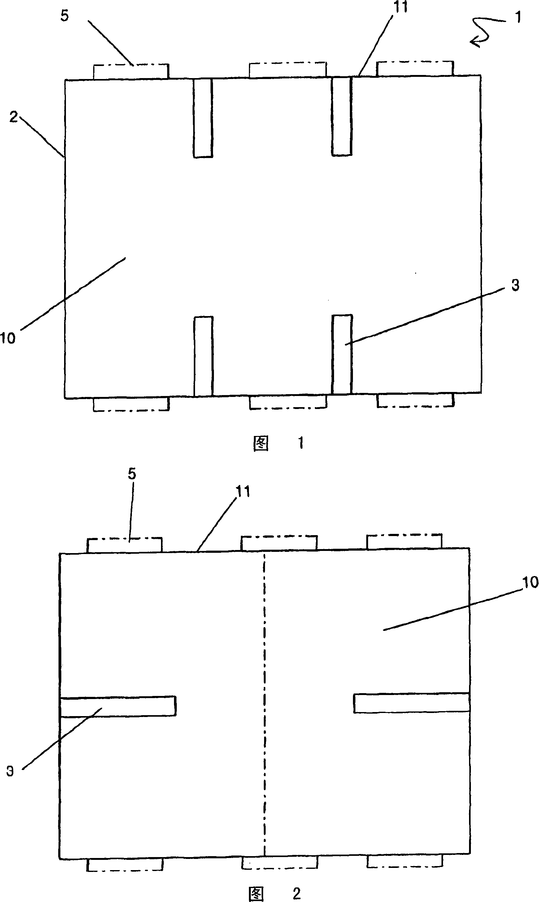
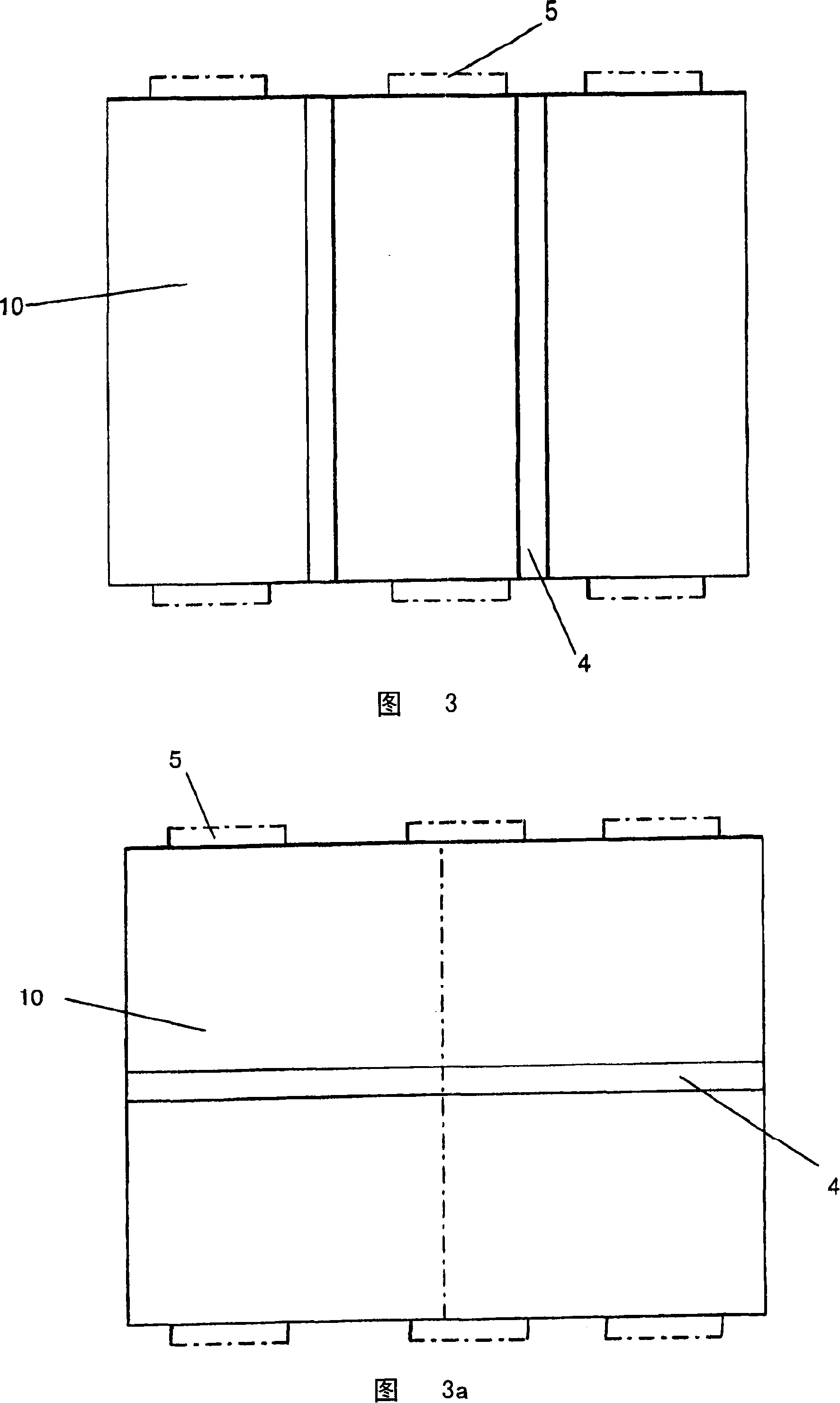
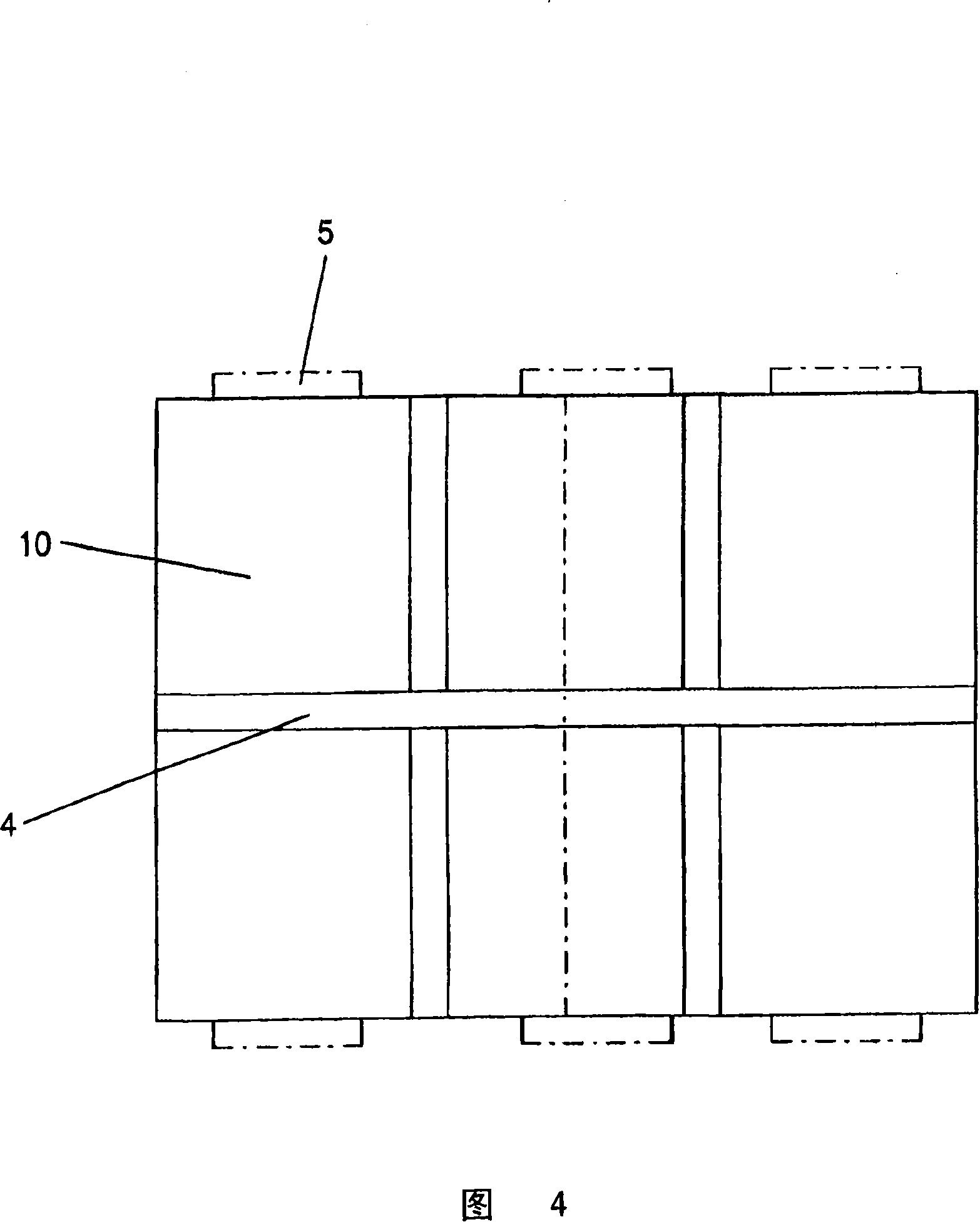
[0038] 1 to 4 show a fluidized bed reactor 1 comprising a membraned, piped wall 2 which encloses a combustion chamber 10 and is cooled by a heat transfer fluid. This wall 2 comprises an extension 3 provided with a pipe. This wall 11 includes an opening 5 communicating with a centrifugal fan (not shown). These extensions can be arranged perpendicular to the wall 11 as shown in FIG. 1, or arranged parallel to the wall 11 as shown in FIG. 2, or as shown in FIG. is divided into three parts, and in Fig. 3a the combustion chamber is divided into two parts. In Fig. 4 the combustion chamber is divided into 6 parts.

[0039] Figure 5 shows possible different types of extensions. These figures generally show possible different configurations depending on the required performance criteria of the exchange surfaces and thermodynamics, which themselves vary with the conditions of the air flow or water vapor fluid circulation. In particular, Figures 5a to 5t include only one end tube for...


PUM


Abstract

The invention relates to a fluidised bed reactor (1) consisting of tube walls (2) with membranes cooled by a coolant, said walls surrounding a firebox (10) and comprising tube extension panels (3) through which a coolant flows by means of single-passage forced circulation. According to the invention, the extension panels (3) are paired.

Description

technical field [0001] The invention relates to fluidized bed reactors such as combustion chambers of boilers. These reactors consist of a combustion chamber usually comprising a filmed, piped wall cooled by a heat transfer fluid, such as a water / air mixture. Background technique [0002] The cross-section of the combustion chamber, which may be rectangular, depends on the rate of rise of the combustion smoke for the combustion chamber to work well. The circumference of the combustion chamber is fixed and the flow rate of the heat transfer fluid circulating in the wall tubes depends on the diameter and spacing chosen for the tubes. The heat exchange surface of four walls can be obtained from the height of the combustion chamber, but the height should be optimized in consideration of reducing the height and the cost of the device, as well as allowing the time required for the chemical reaction between particles to be carried out in the combustion chamber. [0003] Depending...

Claims


Application Information

Patent Timeline
Patent Type & Authority Applications(China)
IPC IPC(8): F22B21/02
CPCF23M5/08F22B31/0007F22B21/34F23C10/18F22B21/02
Inventor J·-X·莫然D·巴廖内
Owner GENERAL ELECTRIC TECH GMBH
Why Eureka
Try Eureka