Holder for cutting tool

A cutting head and shank technology, applied in the direction of tools for lathes, accessories of toolholders, milling cutters, etc., can solve the problem of reduced rigidity of the installation shaft, difficulty in shortening the length of the installation cylinder, and longer protrusion length of the cutting head, etc. problem, to achieve the effect of increasing rigidity, increasing rigidity and shortening distance

Inactive Publication Date: 2008-05-07
MITSUBISHI MATERIALS CORP
View PDF2 Cites 2 Cited by
  • Summary
  • Abstract
  • Description
  • Claims
  • Application Information

AI Technical Summary

Problems solved by technology

[0006] However, if the mounting hole described in Patent Document 2 is formed by the mounting cylinder portion of the tool holder described in Patent Document 1, and the cutting head is detachably mounted, a machine tool applicable to a machine tool equipped with an ATC is configured. In the cutting head replaceable tool, in the tool holder, the internal thread part for screwing the cutting head is formed in the mounting tube protruding from the grip part. Therefore, in order to ensure the length of the internal thread part, it is difficult to shorten the length of the mounting tube part. length
[0007] Moreover, the internal thread portion described in Patent Document 2 is mounted on the front end of the mounting tube portion. Therefore, in such a cutting head replaceable tool, the distance from the front end edge of the outer peripheral surface of the gripping portion to the cutting head, the so-called cutting head The protruding length becomes longer
[0008] In addition, since the internal thread is provided on the mounting cylinder, the cutting head is held at the thinner part, and the cutting head cannot be held firmly. In addition, the rigidity of the mounting shaft itself is also reduced.

Method used


Image

  • Holder for cutting tool
  • Holder for cutting tool
  • Holder for cutting tool

Examples


Embodiment Construction

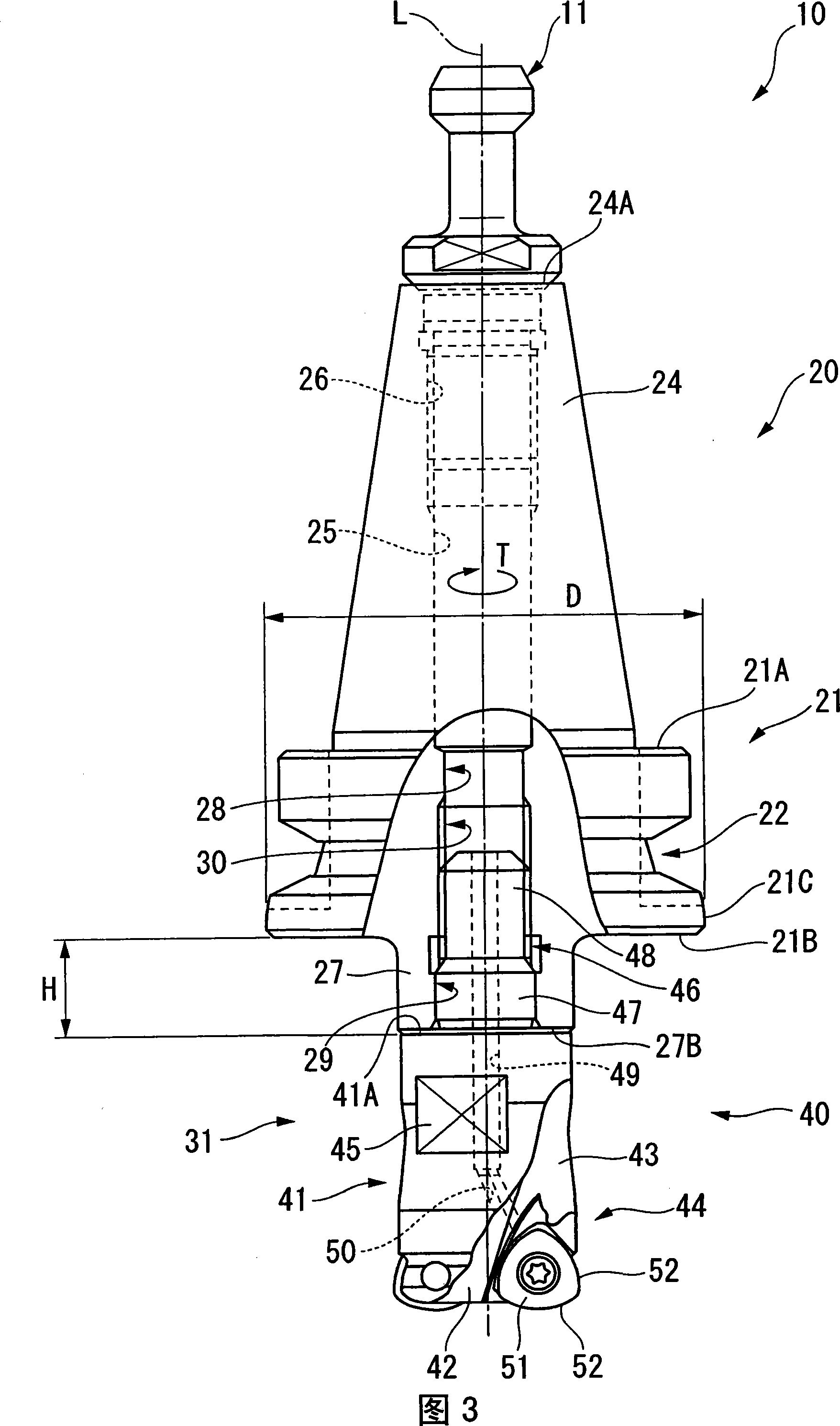
[0052] Hereinafter, embodiments of the present invention will be described with reference to the drawings. 1 and 2 show a tool holder according to this embodiment, and FIG. 3 shows a cutting head replaceable tool equipped with a cutting head.

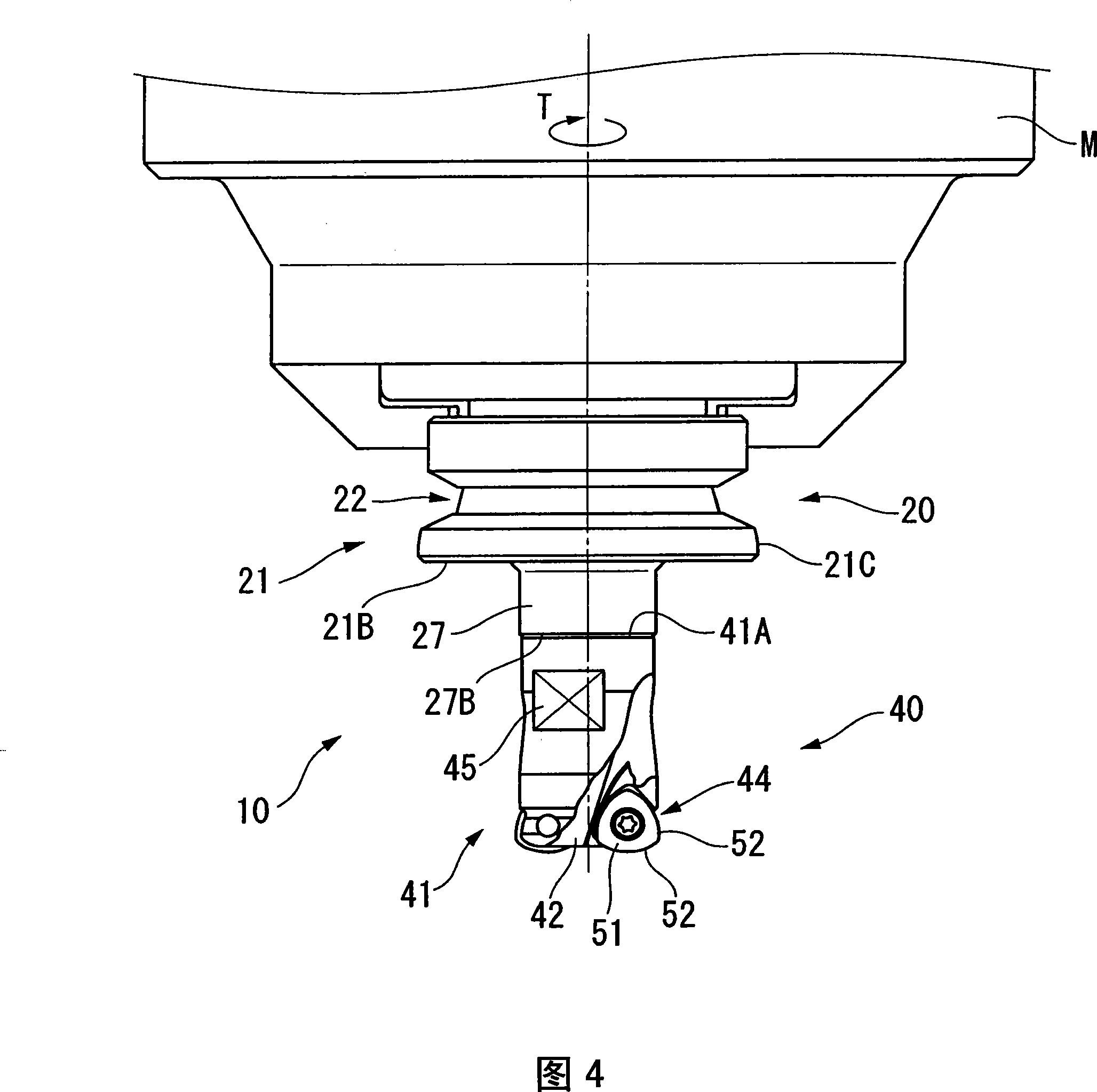
[0053] The cutting head replaceable tool 10 shown in FIG. 3 is mounted on a tool holder 20 mounted on the spindle end of a machine tool M and a cutting head 40 is detachably mounted on the cutter holder 20 .

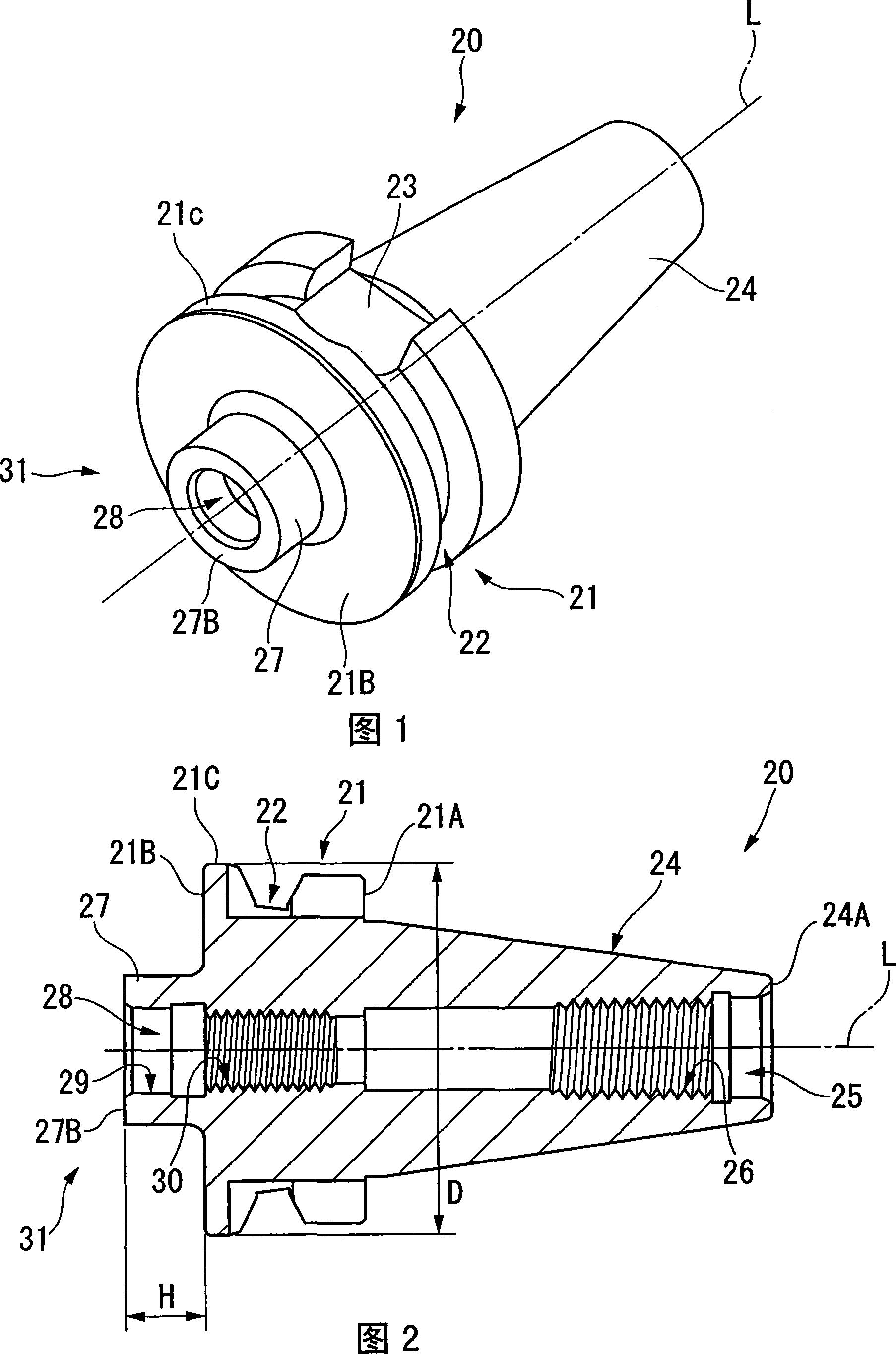
[0054] As shown in FIG. 1 , the tool holder 20 has a substantially multi-stage cylindrical shape extending along the axis L, and includes a gripping portion 21 protruding radially outward around the axis L. As shown in FIG. An annular groove 22 recessed radially inward from the outer peripheral surface is formed in the center portion of the grip portion 21 in the axis L direction. In addition, at the part closer to the proximal side (the upper right side in FIG. 1 and the right side in FIG. 2 ) than the annular groove 22 of the g...


PUM


Abstract

An arbor, method for connecting the arbor and cutting insert as well as cutting insert replaced cutting tool. The arbor, for detachably attaching to a main spindle of a machine tool and holding a cutting insert, includes: an attachment portion for attaching on the main spindle, which has a cylindrical shape extending along the axis L; a gripping portion extending outwardly of the outer periphery of the attachment portion; and a head holding portion for detachably mounting the cutter head, the head holding portion being positioned on the distal end side of the gripping portion, the head holding portion having a mounting hole extending along the axis L toward the base end side, and the mounting hole having a female threaded portion for threadedly connecting the cutter head, the female threaded portion extending to the base end side of the distal edge of the outer peripheral surface of the gripping portion.

Description

technical field [0001] The present invention relates to cutting tools. More specifically, the present invention relates to a tool holder detachably mounted on the main shaft end of a machine tool and holding a cutting head, a method for connecting the tool holder and the cutting head, and a cutting tool formed by connecting the tool holder and the cutting head. Head changeable tools are especially suitable for use on machines with automatic tool changer (ATC) systems. Background technique [0002] Conventionally, as the tool holder, as described in Patent Document 1, for example, there is provided a tool holder including: a mounting portion, which is substantially multi-stage cylindrical extending along the axis, and is mounted on a spindle end of a machine tool; The grip part is located at the front end side of the mounting part, and is flange-shaped and protrudes to the outer peripheral side to be held on the replacement arm of the ATC; the installation tube protrudes fro...

Claims


Application Information

Patent Timeline
Patent Type & Authority Applications(China)
IPC IPC(8): B23Q3/12B23C5/20
CPCB23B31/11B23B2231/0204B23B31/261B23B27/16Y10T279/17948Y10T408/04Y10T408/90993Y10T408/95Y10T409/30952B23C5/20B23Q3/12
Inventor 吉田贵彦大宫司久长谷川健林崎弘章伊藤正昭
Owner MITSUBISHI MATERIALS CORP
Why Eureka
Try Eureka