
Cast-in-situ concrete hollow slab

A hollow slab and cast-in-situ concrete technology, which is applied in the field of cast-in-place concrete hollow slabs, can solve the problems of increasing the thickness of the floor, decreasing the economic performance of the floor, occupying space, etc.

Inactive Publication Date: 2008-05-07
湖南邱则有专利战略策划有限公司
View PDF2 Cites 0 Cited by
  • Summary
  • Abstract
  • Description
  • Claims
  • Application Information

AI Technical Summary

Problems solved by technology

However, after this kind of lightweight carcass is applied to the floor, it needs to occupy a certain space when the pipeline is embedded in the floor, thus greatly increasing the thickness of the floor and reducing the economic performance of the floor.

Method used


Image

  • Cast-in-situ concrete hollow slab
  • Cast-in-situ concrete hollow slab
  • Cast-in-situ concrete hollow slab

Examples


Embodiment Construction

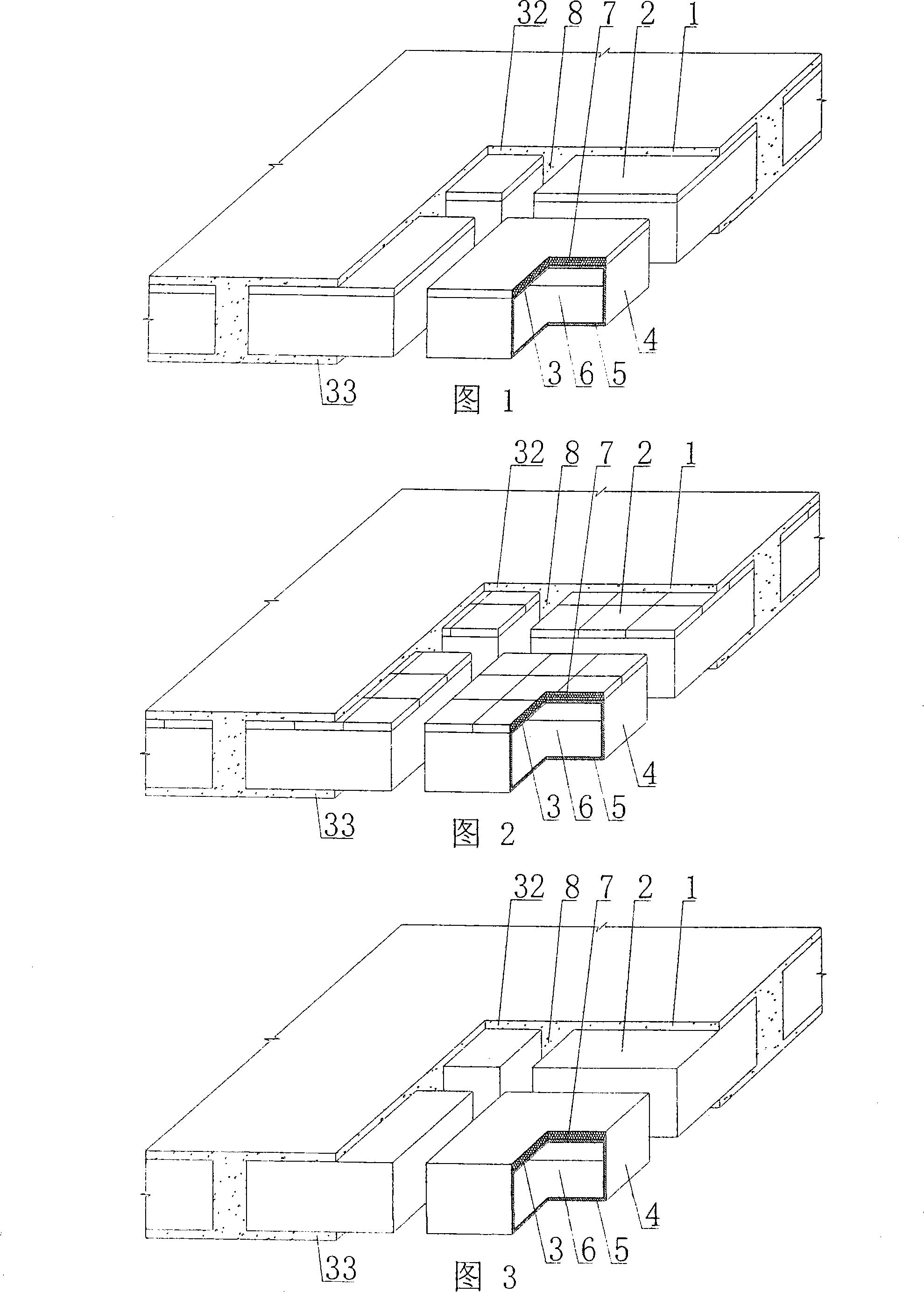
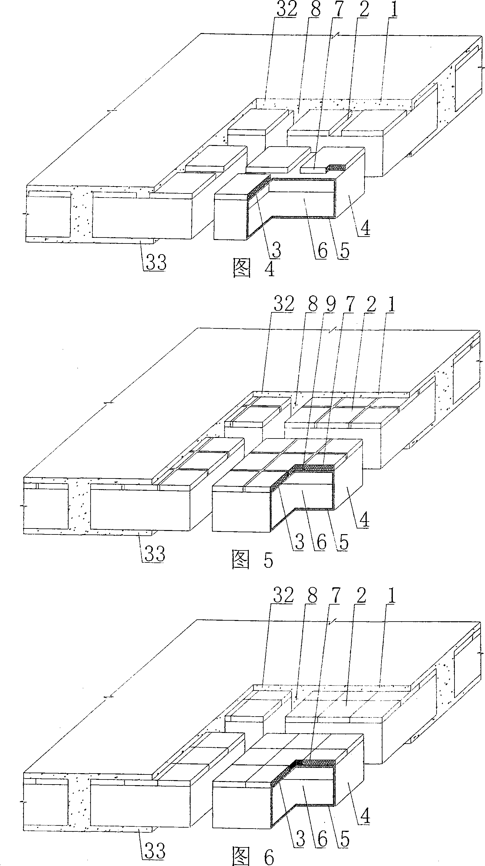
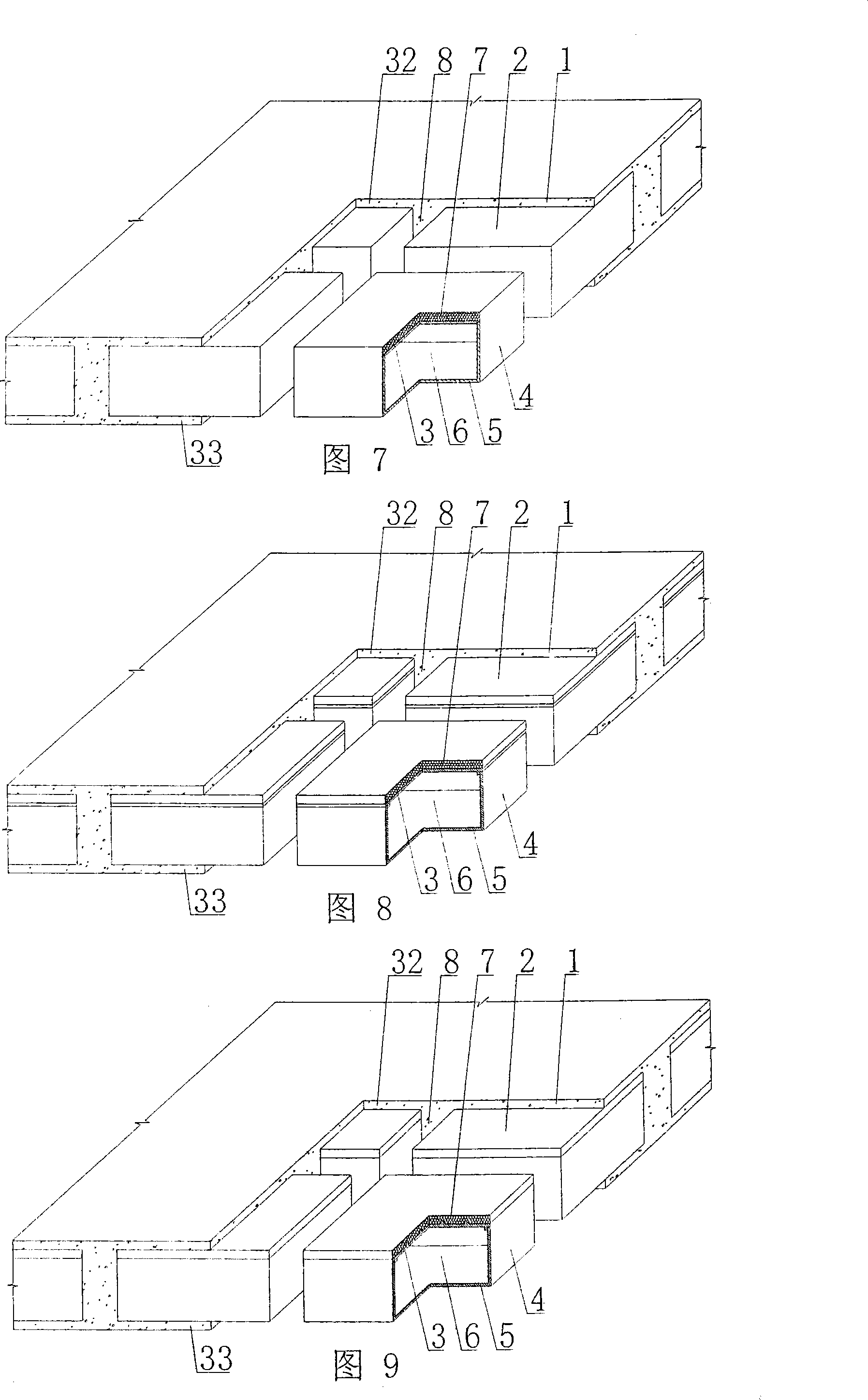
[0086] The present invention will be further described below in conjunction with the accompanying drawings and embodiments.

[0087]As shown in the accompanying drawings, the present invention includes a reinforced concrete 1, a lightweight carcass 2, the lightweight carcass 2 is wrapped in the reinforced concrete 1, and the lightweight carcass 2 includes a top plate 3, a surrounding side plate 4, a lower bottom 5, The cavity 6, the top plate 3, the surrounding side plates 4, and the lower bottom 5 surround each other to form a cavity 6, and at least one of the top plate 3, the surrounding side plates 4 or the lower bottom 5 is wrapped with a soft layer 7, and the lightweight carcass 2 The surrounding side walls 4 are cast-in-place reinforced concrete ribs 8 formed by reinforced concrete 1, which is characterized in that the soft layer 7 is superimposed on the outer surface of the top plate 3, the surrounding side walls 4 or the lower bottom 5, and the top plate 3, The surroun...


PUM


Abstract

The invention relates to a cast-in-place concrete hollow slab, comprising reinforced concrete (1), a light tyre foundation (2), wherein, the light tyre foundation (2) is wrapped in the reinforced concrete (1), and comprises a top plate (3), a plurality of periphery side plates (4), a lower bottom (5) and a hollow cavity (6); the top plate (3), the periphery side plates (4) and the lower bottom (5) are connected together to form the hollow cavity (6); a soft layer (7) is at least wrapped in one of the top plate (3), the periphery side plates (4) or the lower bottom (5), the cast-in-place reinforced concrete ribs (8) formed with reinforced concrete (1) are arranged among the periphery side walls (4) of the light tyre foundation (2). The invention is characterized in that the soft layer (7) is superposed on the external surface of the top plate (3), the periphery side plates (4) or the lower bottom (5), the top plate (3), the periphery side plates (4), or the lower bottom (5) are hard layers, a reinforced layer (10) is arranged on the external surface of the soft layer (7) for preventing the damage of the soft layer. Thereby, the invention is suitable for the hollow building roofs, house roofs, walling, foundation bottom plates and vierendeel bridges of the cast-in-place reinforced concrete or the prestressed reinforced concrete.

Description

[0001] This application is a divisional application of an invention patent application with an application date of November 10, 2005, an application number of 200510119894.7, and a title of "a cast-in-place concrete hollow slab". (1) Technical field [0002] The invention relates to a cast-in-place concrete hollow slab. (2) Background technology [0003] At present, the cast-in-situ concrete hollow floor is a widely used floor structure. The soft permanent tire mold filled therein has various hollow tubes and boxes, and the boxes are hollow or solid. For example, the patent No. ZL99249798.1, which the applicant applied for on November 29, 1999, is a utility model patent named "fiber-reinforced thin-walled member for reinforced concrete filling", which discloses a thin-walled lightweight carcass, including The upper board, the surrounding side walls and the lower bottom form a polyhedral cavity, and the upper board, the surrounding side walls and the lower bottom contain fibe...

Claims


Application Information

Patent Timeline
IPC IPC(8): E04B5/17E04G11/36
Inventor 邱则有
Owner 湖南邱则有专利战略策划有限公司
Features
  • Generate Ideas
  • Intellectual Property
  • Life Sciences
  • Materials
  • Tech Scout
  • Unparalleled Data Quality
  • Higher Quality Content
  • 60% Fewer Hallucinations
Learn More