Supercharge Your Innovation With Domain-Expert AI Agents!

Motor structure

A motor and stator structure technology, applied in the direction of structural connection, magnetic circuit shape/pattern/structure, and winding conductor shape/pattern/structure, etc., can solve the problems of inconvenient manufacturing and assembly, difficult alignment, and easy falling off of coils.

Inactive Publication Date: 2008-05-07
SUNONWEALTH ELECTRIC MACHINE IND
View PDF0 Cites 0 Cited by
  • Summary
  • Abstract
  • Description
  • Claims
  • Application Information

AI Technical Summary

Problems solved by technology

[0007] However, the stator of the above-mentioned motor structure must be respectively fixed on the outer peripheral wall of the housing base 11 through an even group of coils 13, thus deriving the following disadvantages:
[0008] (1) Manufacturing and assembling are inconvenient: because the stator of the conventional motor structure must fix the even groups of coils 13 on the outer peripheral wall of the housing base 11 respectively, so when the motor structure is manufactured, the even groups of coils 13 must be wound first, and then Fix the even groups of coils 13 on the outer peripheral wall of the housing 11 one by one. If the number of coils 13 is two groups, the process of fixing the coils 13 must be repeated twice. If the number of coils 13 is four groups, the process of fixing the coils 13 must be repeated four times. The process of coil 13 not only requires several more processes in manufacturing, but also is inconvenient in assembly
[0009] (2) The coil is easy to fall off: the coil 13 of this conventional motor structure is fixed on the outer peripheral wall of the housing base 11, and only relies on the fixing member 113 to stick to it. If it is affected by the vibration generated by the rotation of the rotor 10 for a long time, it is easy. and fall off
[0010] (3) Difficulty in alignment: The even group of coils 13 and the motor induction drive assembly 14 of this conventional motor structure are independently fixed on the outer peripheral wall of the housing 11, so when assembling, special attention must be paid to whether there is accurate alignment between these components. Otherwise, it will cause difficulty in starting the motor

Method used


Image

  • Motor structure
  • Motor structure
  • Motor structure

Examples


Embodiment Construction

[0026] The invention relates to a motor structure, which arranges components such as coils, motor induction drive components, etc. on a flexible substrate, so that when assembling the stator structure, the steps of assembling and fixing the coils and motor induction drive components and aligning them respectively can be omitted The process makes the manufacture and assembly of the motor structure easier and more convenient.

[0027] Two preferred implementation forms of the present invention are listed below and described with accompanying drawings.

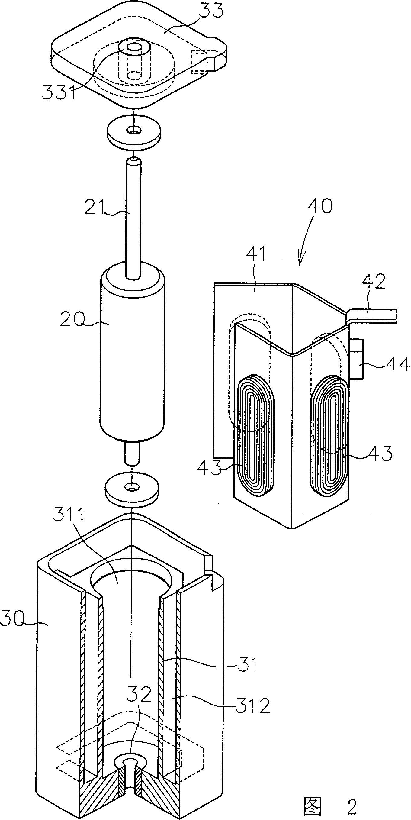
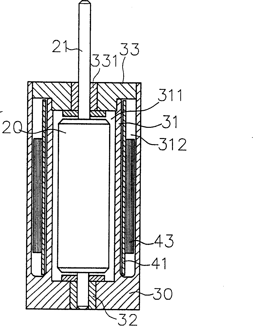
[0028] As shown in Figure 2, image 3 and Figure 4 As shown, it is the first embodiment of the present invention, which includes:

[0029] A rotor 20 is combined with a rotating shaft 21 .

[0030] A shell seat 30, the interior of the shell seat 30 is hollow, and a ring wall 31 is provided. A rotor placement groove 311 is formed inside the ring wall 31, and a stator placement groove 312 is formed on the outer periphery of the...


PUM


Abstract

The present invention relates to a motor structure, including a shell base, the inside of the shell base is provided with an annular wall, the center of the annular wall is provided with a rotor placing slot for placing a rotor, the periphery of the annular wall is a stator placing slot; a stator structure, the stator structure is provided with a flexible base plate, a coil and a motor induction drive module are arranged on the flexible base plate and are electrically connected, the flexible base plate is bent according to the shape of the stator placing slot and placed in the slot. Therefore, the present invention can save the separate assembly, fixing and contra-positioning procedures of coil, motor induction drive module and other components when assembling the stator structure, thus making the production and assembly of the motor structure simpler and more convenient.

Description

technical field [0001] The invention relates to a motor structure, in particular to a practical motor structure that can be conveniently processed and assembled to simplify the manufacturing and assembling process of the motor structure, reduce manufacturing cost and improve production efficiency. Background technique [0002] like figure 1 As shown, the conventional motor structure includes: [0003] A rotor 10 is combined with a rotating shaft 101 . [0004] A shell base 11, inside the shell base 11 is provided with a rotor placement groove 111, for the rotor 10 to be placed therein, and a support piece 112 is provided at the bottom of the rotor placement groove 111, the support piece 112 can be a bearing or a shaft sleeve... and other components, One end of the rotating shaft 101 for supporting the rotor 10 rotates at its center. [0005] A cover body 12 is arranged on the top of the housing seat 11 in a corresponding manner, and a support member 121 is arranged in the...

Claims


Application Information

Patent Timeline
IPC IPC(8): H02K5/00H02K5/04H02K1/12H02K3/04H02K11/00H02K11/33
Inventor 洪银树尹佐国
Owner SUNONWEALTH ELECTRIC MACHINE IND
Features
  • R&D
  • Intellectual Property
  • Life Sciences
  • Materials
  • Tech Scout
  • Unparalleled Data Quality
  • Higher Quality Content
  • 60% Fewer Hallucinations
Learn More