

Brushless motor
A technology of brushless motors and motors, applied in the direction of electric components, electrical components, electromechanical devices, etc., can solve problems such as difficulty in implementation, difficulty in ensuring connection strength, and impractical fixation of bonding methods, so as to prevent splashing, cheap components, and The effect of improving convenience
- Summary
- Abstract
- Description
- Claims
- Application Information
AI Technical Summary
Problems solved by technology
Method used
Image

Examples
Embodiment 1
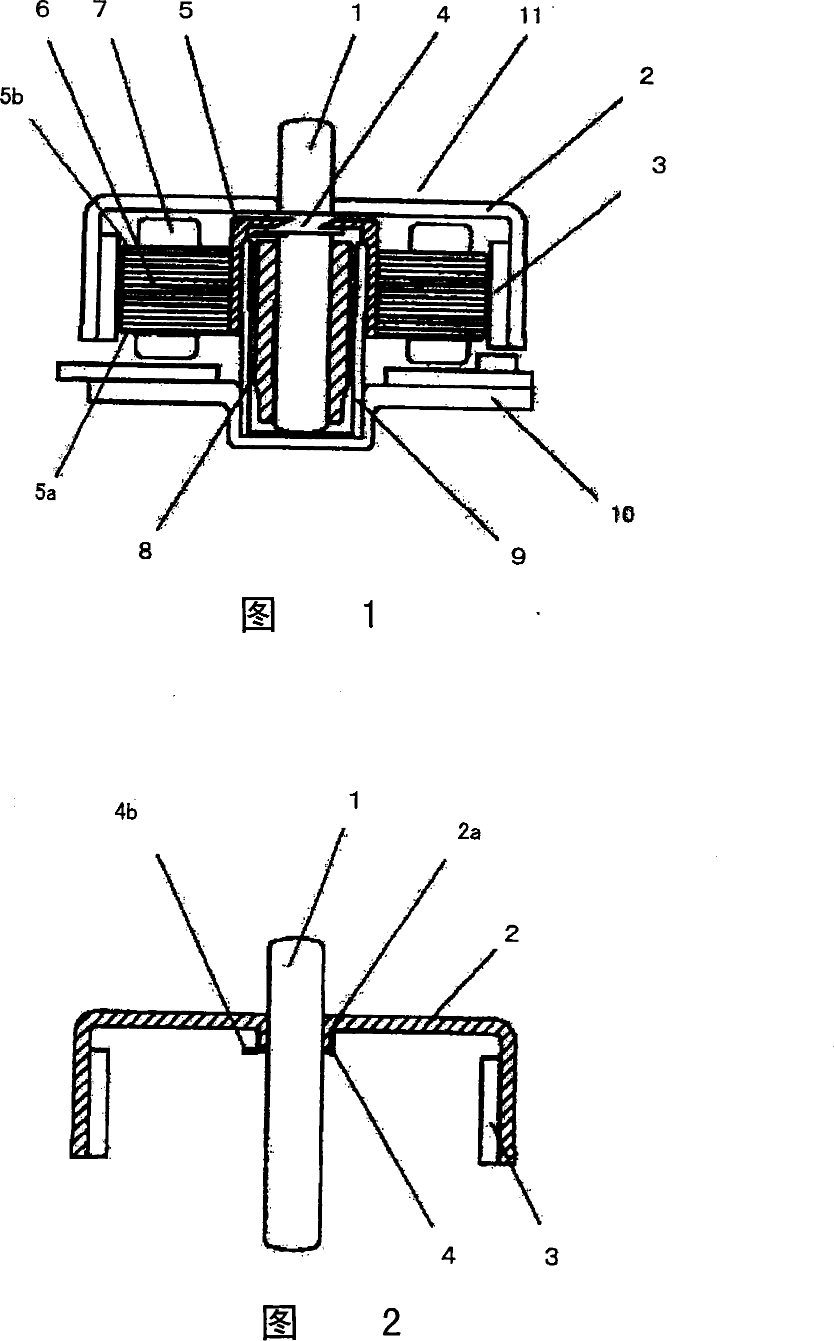
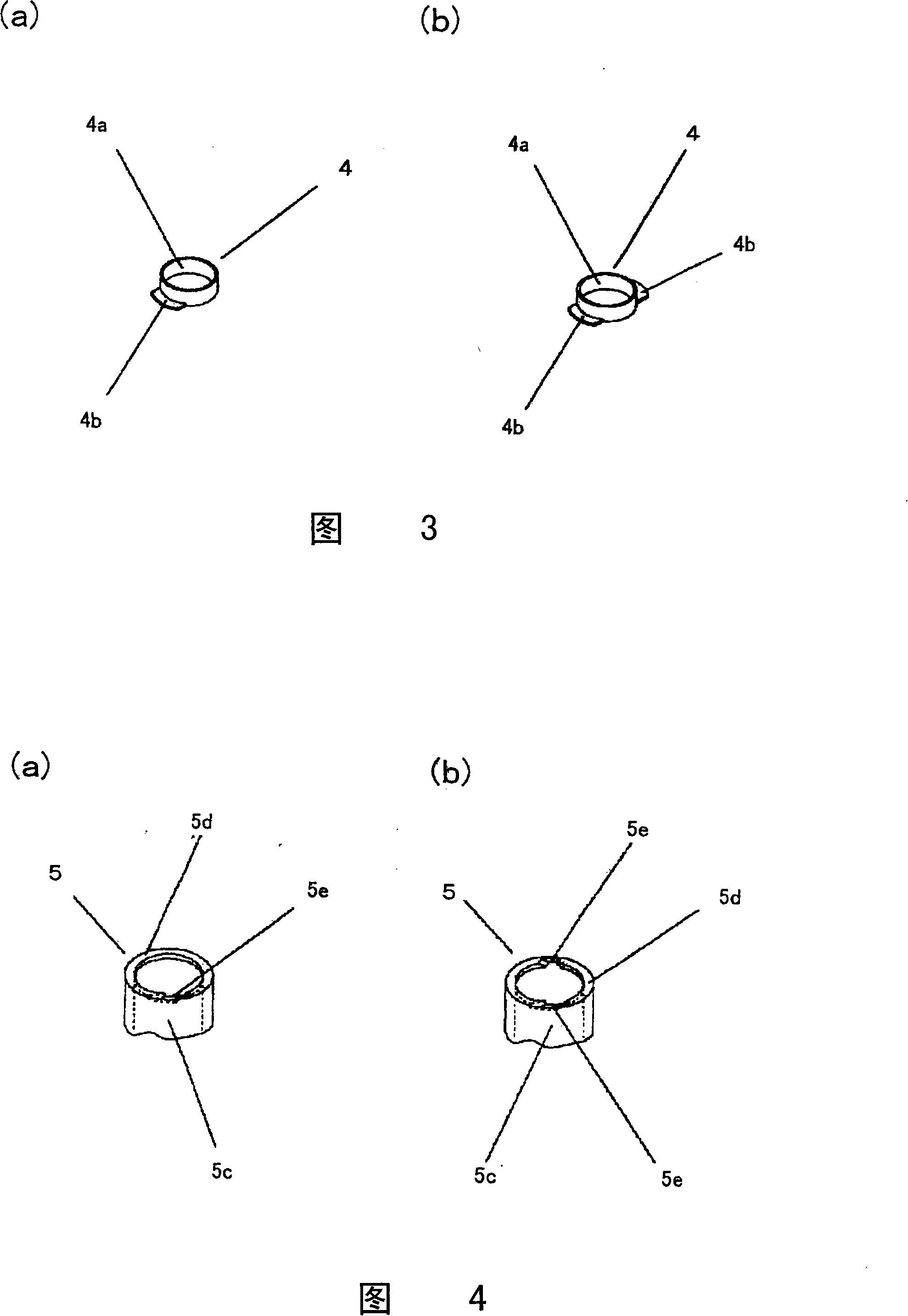
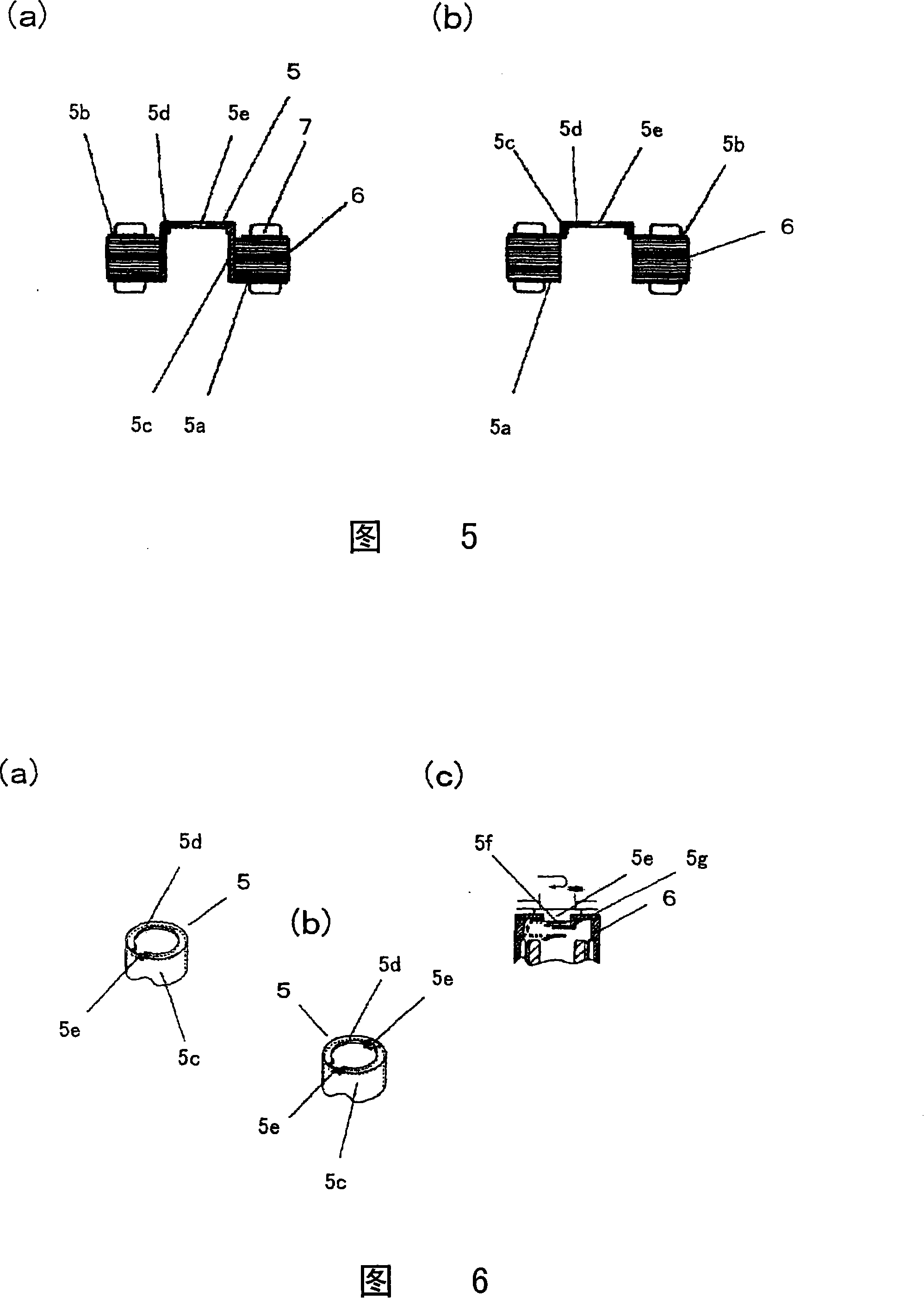
[0041] As shown in FIG. 1 , a brushless motor 11 is composed of a rotor assembly and a stator assembly. The rotor assembly consists of a rotor frame 2 with a shaft 1 fixed in the center, and a rotor mounted on the inner peripheral side of the rotor frame 2 . The magnet 3 and the fastening part 4 installed on the fixed part of the above-mentioned shaft 1 on the top surface of the rotor frame case 2 are constituted; the stator assembly is composed of a bearing 8 that freely rotatably supports the above-mentioned shaft 1, and the bearing 8 is held on the The cylindrical bearing housing 9 on the inner peripheral side, the motor mounting plate 10 fixedly holding the bearing housing 9 at the center by press fitting or the like, the stator core 6 mounted on the outer peripheral side of the bearing housing 9, and the gasket A coil 7 wound by insulating members 5 a and 5 b mounted on the surface of the stator core 6 and a fall-off prevention member 5 mounted on the stator core 6 are con...
Embodiment 2
[0048] 9, 10(a), and 10(b) show a brushless motor of the present invention (Example 2).
[0049] As shown in FIG. 9 , the brushless motor includes a rotor portion 33 and a stator portion 40 .
[0050] The rotor part 33 has: a turntable part 28 for placing the disc, a rotor frame case 29, a disc alignment member 30 supporting the disc together with the turntable part 28, a rotor magnet 31 mounted on the rotor frame case 29, And the shaft 1 fixed to the center of the above-mentioned rotor frame case 29 .
[0051] The stator part 40 has: a bearing 8 supporting the above-mentioned shaft 1, a bearing housing 9 holding the bearing 8, an axial thrust stopper 36 supporting the shaft 1 in the axial direction, and a coil wound with a rotor magnet 31 opposite to the above-mentioned rotor magnet 31. 37 iron core 38, and the motor mounting plate 10 holding the above-mentioned bearing housing 9.
[0052] The bearing housing 9 is integrally formed into a substantially cylindrical shape, an...
Embodiment 3
[0056] Fig. 11(a) and Fig. 11(b) show Embodiment 3 of the present invention.
[0057] In Fig. 9, the bottom of the recessed part 10a of the motor mounting plate 10 is flat, and the base end of the bearing housing 9 is fitted in the recessed part 10a only by its outer circumference, but in this embodiment, the difference from it (Example 2) is only A groove 41 into which the proximal end of the bearing housing 9 fits is formed at the bottom of the recessed portion 10a. Other configurations of the brushless motor are the same as in FIG. 9 .
[0058] Specifically, as shown in FIG. 11( a ), a groove 41 is integrally provided on the bottom surface of the recess 10 a formed on the motor mounting plate 10 . The axial thrust baffle 36 is provided on the inner side than the groove 41 .
[0059] In addition, as shown in FIG. 11( b ), protrusions 42 at several positions are formed in the groove 41 so as to have a height lower than the inner diameter side wall surface 43 of the fitting ...
PUM
 Abstract
Description
Claims
Application Information