Air ion conveyance device and air ion conveyance system

A technology of air ion and conveying device, which is applied in the direction of ventilation system, electrical components, space heating and ventilation, etc., and can solve the problem of mutual offset of ion generation

Inactive Publication Date: 2008-05-07
THE SHIMIZU CONSTRUCTION CO LTD +1
View PDF3 Cites 8 Cited by
  • Summary
  • Abstract
  • Description
  • Claims
  • Application Information

AI Technical Summary

Problems solved by technology

[0009] However, as shown in FIG. 16-1, when the positive ion generating device 104a for generating positive ions and the negative ion generating device 104b for generating negative ions are installed in a state where they are in direct contact with each other, there is a possibility that the generated amounts of ions cancel each other out. question

Method used


Image

  • Air ion conveyance device and air ion conveyance system
  • Air ion conveyance device and air ion conveyance system
  • Air ion conveyance device and air ion conveyance system

Examples


Embodiment approach 1

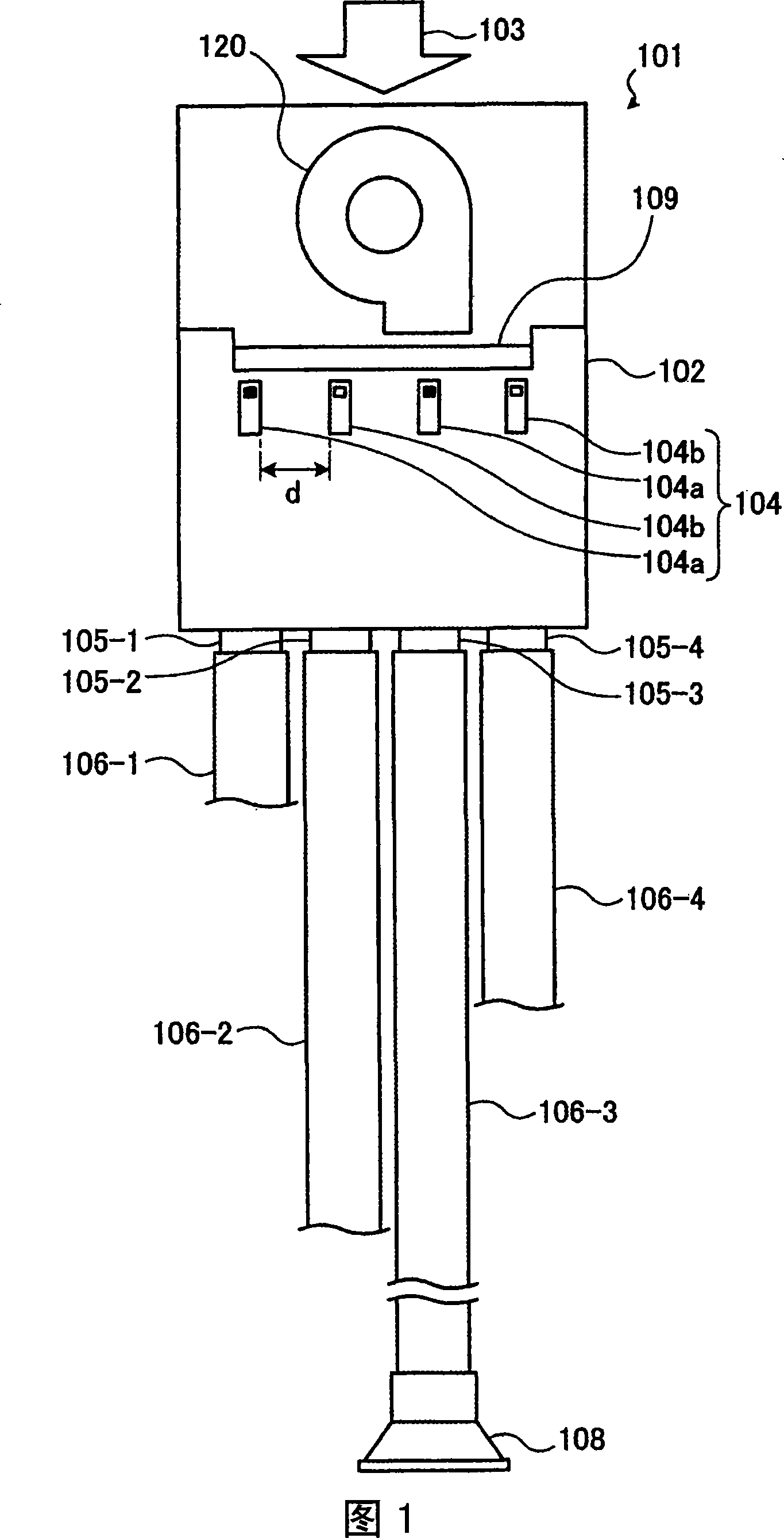
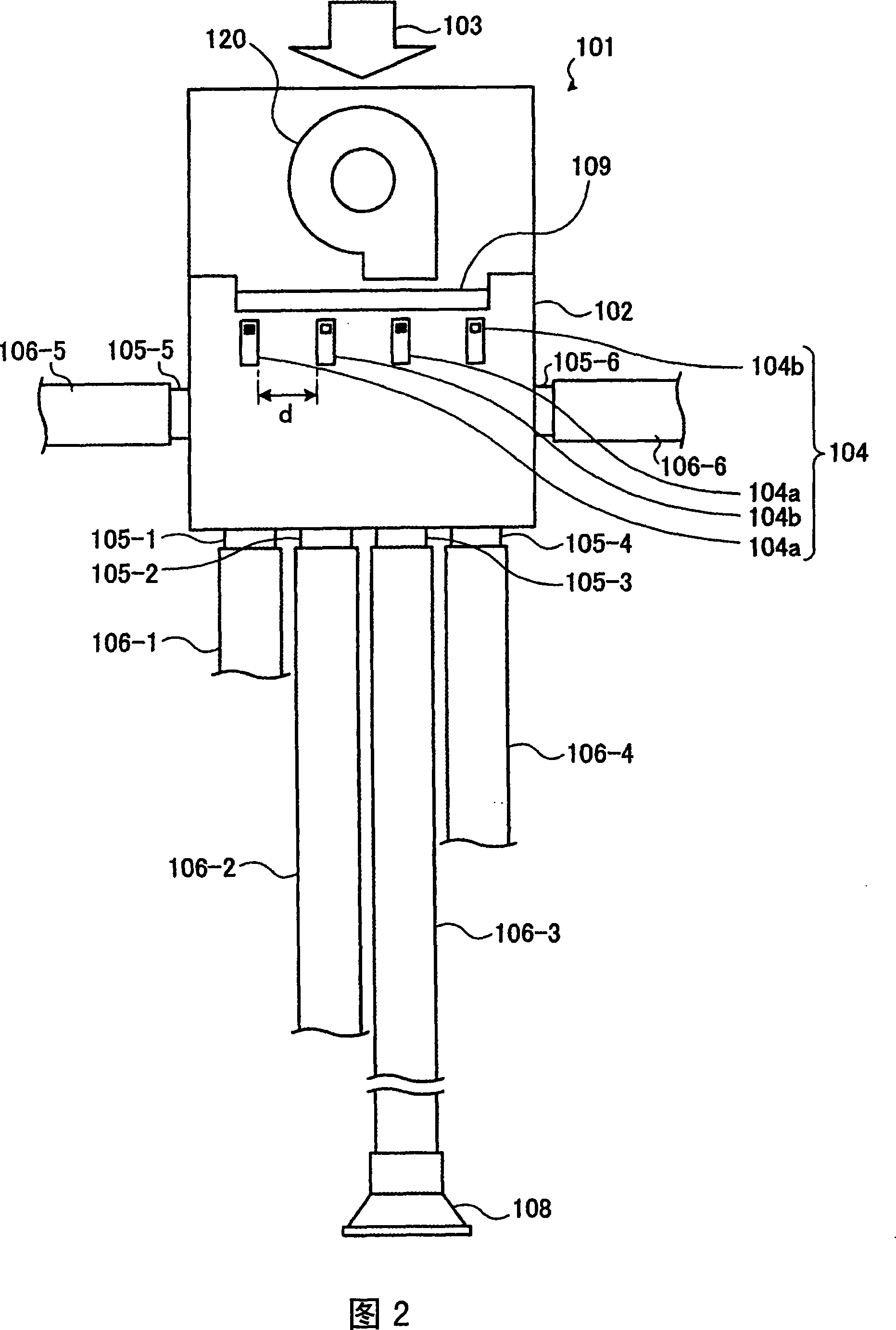
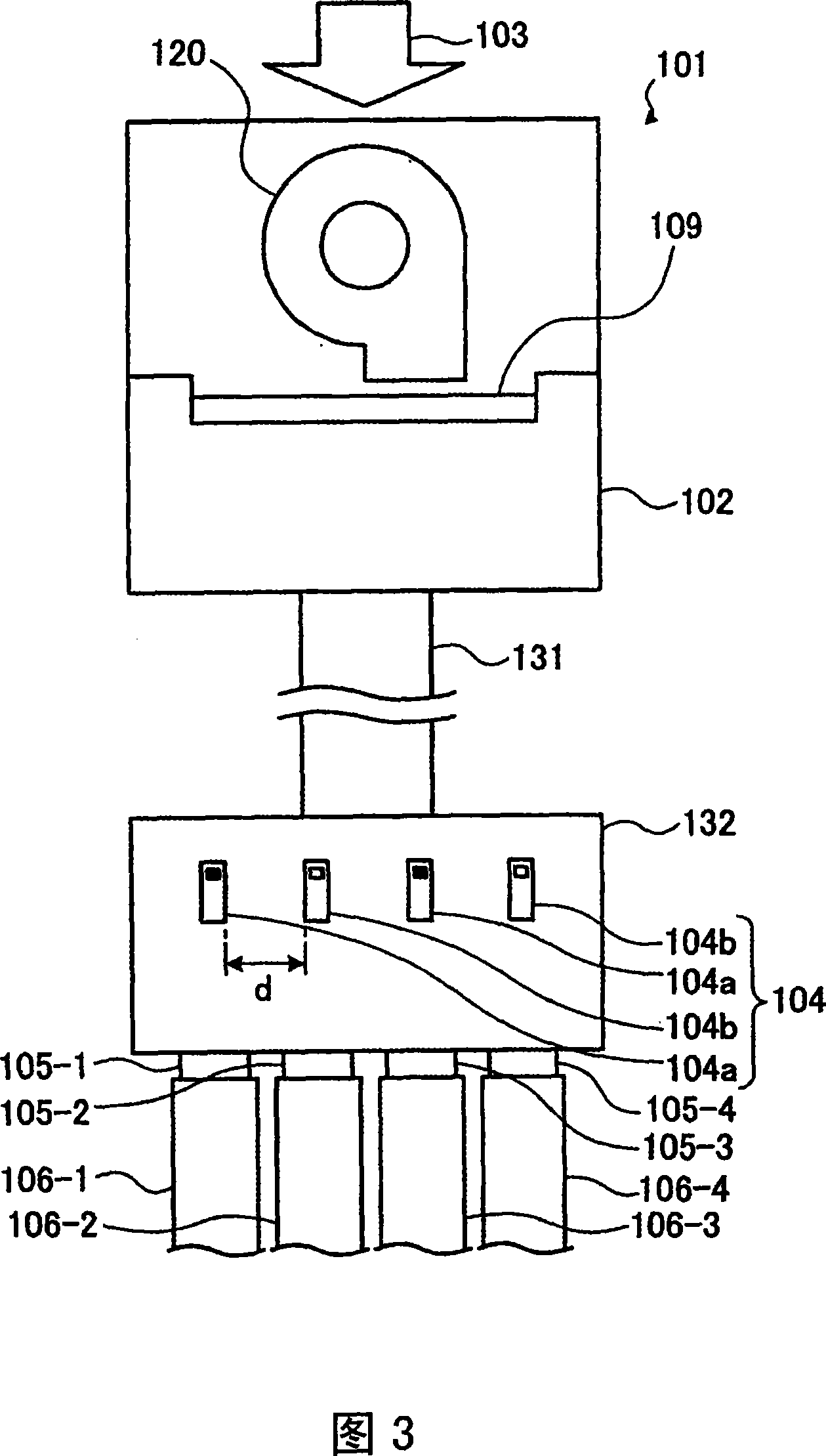
[0202] FIG. 1 is a schematic configuration diagram showing an air conditioning system to which an air ion transport device according to Embodiment 1 of the present invention is applied.

[0203] As shown in FIG. 1 , the air conditioning system of this embodiment is used, for example, in air conditioners, etc., to deliver air to rooms such as houses, for example, it is provided with: Positive ion generators (air ion generators) 104a that generate positive ions in the air 103 and negative ion generators (air ion generators) 104b that generate negative ions maintain the air ion generator units 104 that are alternately arranged at a predetermined interval d; The air ducts 106 that are connected to the joints (four in this embodiment) 105-1 to 105-4 on the casing 102 and independently deliver air to a plurality of rooms (four rooms in this embodiment) -1 to 106-4; the control device, not shown, which controls the air ion generating device, adjusts the presence or absence of air ion...

Embodiment approach 2

[0263] 17 to 24 are schematic diagrams showing an air ion transport device according to Embodiment 2 of the present invention. In addition, the air ion delivery device in this embodiment is generally applied to, for example, a ventilation system that replaces air in predetermined areas such as apartments, medical care, elderly health facilities, offices, and factories, or an air conditioning system that performs air conditioning in predetermined areas, and conducts construction. Air conditioning systems for air conditioning of various buildings such as equipment and vehicles (passenger cars, buses, trains, etc.).

[0264] The air ion transport device shown in FIG. 17 constitutes an air ion transport unit having a blower 301 and an air ion generator 302 . The air blower 301 has a box-shaped casing 311 and a blower 312 accommodated in the casing 311 . An air suction port 311 a is provided at a portion on the air suction side of the air blower 312 in the housing 311 . In additi...

Embodiment approach 3

[0304] 25 is a schematic configuration diagram showing an air ion transport system according to Embodiment 3 of the present invention.

[0305] The air ion delivery system 400 of the present invention is used, for example, by air conditioners, etc., to deliver air ions to rooms such as houses, and includes: a casing 402 installed in a centralized ventilator 401, so that the air supplied from the outside contains negative ions or positive ions. The air ion generating device 404 of ions or these two kinds of ions; the air duct 406 that is connected to the joint 405 that is arranged on the casing, and independently sends air ions to a plurality of rooms (four rooms in this embodiment)- 1 to 406-4; the control device 407 for controlling the air ion generating device usually adjusts the generation of air ions or the amount of ion generation through the control device according to the requirements of each room. In addition, reference numeral 408 denotes a blower unit that blows air ...


PUM


Abstract

The present invention provides an air ion conveyance device as well as an air ion conveyance system, for example, for an air conditioning facility and conveys air ions to rooms of a house etc. The air ion conveyance device has an air ion production device unit, air ducts, and a control device. The air ion production device unit is provided in a housing of a centralized ventilation device and has positive ion production devices and negative ion production devices that are alternately arranged with a spacing in between, the positive ion production devices generating positive ions in air fed from the outside, the negative ion production devices generating negative ions in the air. The air ducts are connected to joints provided at the housing and individually conveys air to rooms. The control device controls the air ion production device unit. The control device regulates, according to a request from each room, whether or not to produce air ions or the amount of production of ions.

Description

technical field [0001] The present invention relates to an air ion transport device and an air ion transport system for supplying air ions containing negative ions or positive ions in the air to a desired site. Background technique [0002] In recent years, for example, in houses with high airtightness and high heat insulation, indoor air cannot be sufficiently replaced with outdoor air, so there is a ventilation device that actively ventilates each room. This device includes a chamber-type air blower configured to supply air from an air supply box by a blower, and suck air to an exhaust box by the blower. There are multiple pipe holes on the opening of the chamber blower, so that the pipe holes are directly connected to the air supply ports and exhaust ports of each room, and each room is equipped with dedicated air supply pipes and exhaust pipes. . Moreover, an anion generating device is arranged on the air supply box of the chamber blower to its pipe holes, and an air v...

Claims


Application Information

Patent Timeline
Patent Type & Authority Applications(China)
IPC IPC(8): A61L9/22H01T23/00F24F7/00
Inventor 山口一布施幸则安坂务橘雅哉栗原隆高桥谕史杉冈亮一
Owner THE SHIMIZU CONSTRUCTION CO LTD
Why Eureka
Try Eureka