Derailment preventing guard

A technology of safe rails and rails, applied in roads, rails, buildings, etc., can solve safety problems, loading and unloading troubles, troublesome problems, etc.

Inactive Publication Date: 2008-05-07
CENTRAL JAPAN RAILWAY COMPANY +1
View PDF0 Cites 3 Cited by
  • Summary
  • Abstract
  • Description
  • Claims
  • Application Information

AI Technical Summary

Problems solved by technology

That is to say, the anti-derailment guide member 132 shown in Figure 31 constitutes the work obstacle of the sleeper tamper carrying out the ballast tamping operation and the track correction vehicle or the maintenance car, but the existing anti-derailment guide member is to use many bolts The fastening structure combined with the nut makes its assembly and disassembly very troublesome and troublesome
And in order not to form an obstacle to the ballast tamping operation of the sleeper tamping machine and the work of the track correction vehicle or the maintenance vehicle, it is necessary to manually move the anti-derailment guide member of the heavy object to outside the specified distance beside the line, so There are security concerns when moving it
[0017] Equally, the safety rail 113 and 114 on the position shown in Fig. 28 (a), (b) also constitute the obstacle that the sleeper tamper carries out ballast tamping operation and track correction operation, in order not to affect these works, it is necessary to use Manually move the safety track, which is a heavy object, to a specified distance beside the line, so there is a safety problem when moving it

Method used


Image

  • Derailment preventing guard
  • Derailment preventing guard
  • Derailment preventing guard

Examples


Embodiment Construction

[0170] Embodiments of the present invention will be described below with reference to the drawings. However, the present invention is not limited to the following embodiments, and the present invention can be appropriately changed and modified within the range not departing from the technical scope of the present invention.

[0171] 1. Embodiment of the first invention

[0172] first embodiment

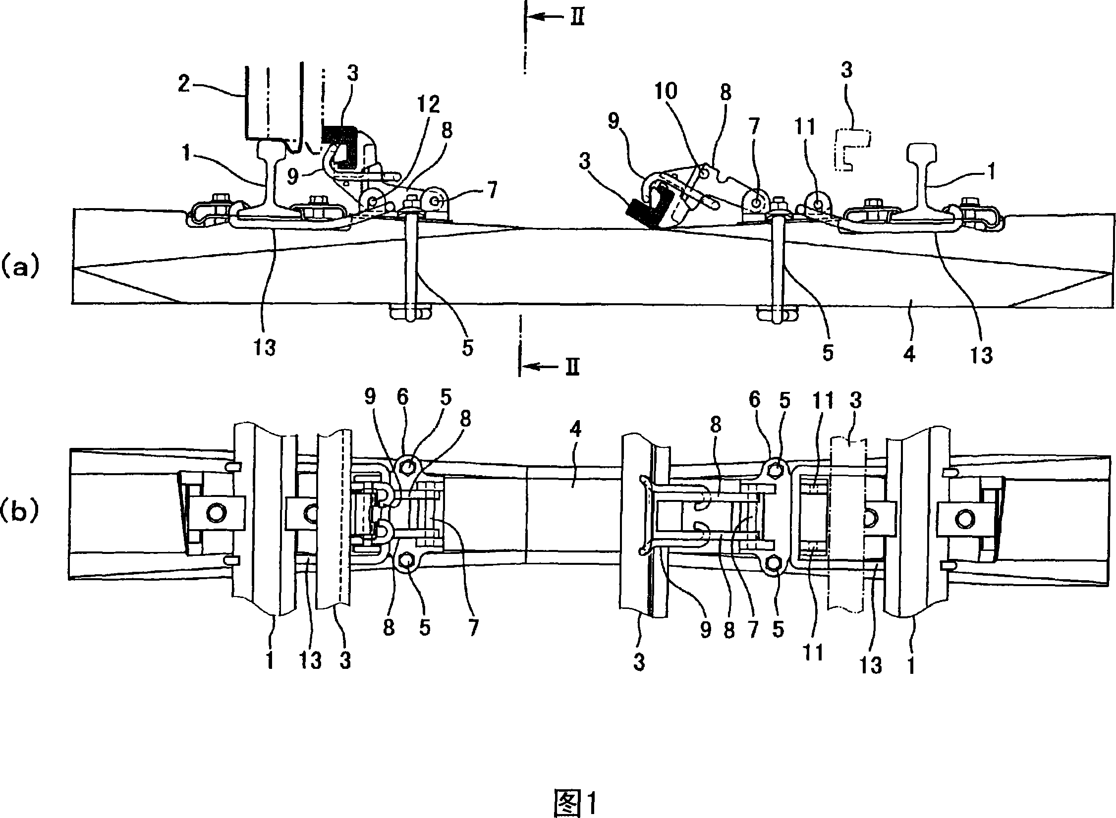
[0173] Fig. 1 (a) is the side view of the first embodiment of the structure of using the anti-derailment guide device of the first invention on the railway line (track with ballast), and Fig. 1 (b) is the side view of Fig. 1 (a). floor plan.

[0174] In Fig. 1 (a), (b), 1, 1 are main track, and 2 are wheels. The guide member 3 is arranged in parallel to the main line rails 1, 1 in the rail space.

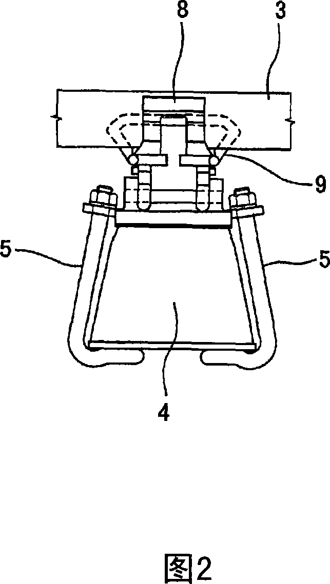
[0175] The support member 6 is fixed to the sleeper 4 with the bolt 5 . Can take the central shaft 7 that is supported in support member 6 as the center of rotation, the spring member 9...


PUM


Abstract

The present invention provides a derailing prevention guard enabling the easy retreat to the outside of a ballast tamping operation area and a vehicle operation area to secure safety. The guard comprises guard members (3) disposed inside tracks and support members (6) fixed to a sleeper (4) or a slab track. The guard members (3) are held by holders (8) rotatable about center shafts (7) supported on the support members (6) between a main rail (1) sides and the inner sides of the tracks on the sleeper (4) or the slab track, the holders (8) are rotated to the main rail (1) side about the center shaft (7) on the sleeper (4) or the slab track, and the support members (6) and the holders (8) are locked with bolts (12). The guard member (3) can be retreated to the inside of the tracks by rotating it about the center shaft (7) to the inside of the tracks on the sleeper (4) or the slab track.

Description

technical field [0001] The present invention relates to a safety device for a vehicle, in particular, to a guide device that prevents a wheel from deviating from a main line track and a guide device that prevents a derailed vehicle from escaping out of the track. Background technique [0002] The present invention relates to a device that enables vehicles to run safely, specifically, it is a guide device that prevents the wheels from deviating from the main line track, that is, a so-called anti-derailment guide device, and a guide device that prevents a derailed vehicle from escaping out of the track, that is, a so-called Safety rail installation. [0003] Therefore, in the following, the outline of the derailment prevention guide and the safety rail device will be described first, and then the relationship between the railway maintenance work and the derailment prevention guide and the safety rail device will be described. [0004] (1) Anti-derailment guide [0005] For e...

Claims


Application Information

Patent Timeline
IPC IPC(8): E01B5/18
Inventor 关雅树可知隆船田智巳入江隆昭小西胜成花崎哲也
Owner CENTRAL JAPAN RAILWAY COMPANY
Why Eureka
Try Eureka