
Device for locking traveler of tyre builder

A tire building machine and locking device technology, applied to tires, other household appliances, household appliances, etc., can solve the problems of inconsistent stretching of the bladder, affecting the symmetry and balance of the tire, and high labor intensity of workers.

Active Publication Date: 2008-05-14
GUILIN RUBBER MACHINERY CO LTD
View PDF0 Cites 2 Cited by
  • Summary
  • Abstract
  • Description
  • Claims
  • Application Information

AI Technical Summary

Problems solved by technology

The capsule is large in size and takes a long time to inflate, and in order to align the carcass tube traveler, the capsule needs to be repeatedly inflated and deflated several times during the operation process, and the labor intensity of the workers is high
In particular, due to repeated inflation and deflation, the stretching of the bladder is inconsistent, which affects the symmetry and balance of the produced tires, which is not conducive to improving the quality of the tires, and will reduce the service life of the tires
The capsule itself is a vulnerable part with low safety performance
It is also difficult to replace the capsule after wear and aging
In particular, the volume of the capsule used in the giant tire is huge, the manufacturing precision is high, molding and vulcanization are very difficult, and the yield is low, so the cost of a single capsule is relatively high.
If the traveler bladder is repeatedly inflated and deflated to lock the carcass tube, the service life of the bladder will be reduced and the production cost of the tire will be increased.

Method used


Image

  • Device for locking traveler of tyre builder

Examples


Embodiment Construction

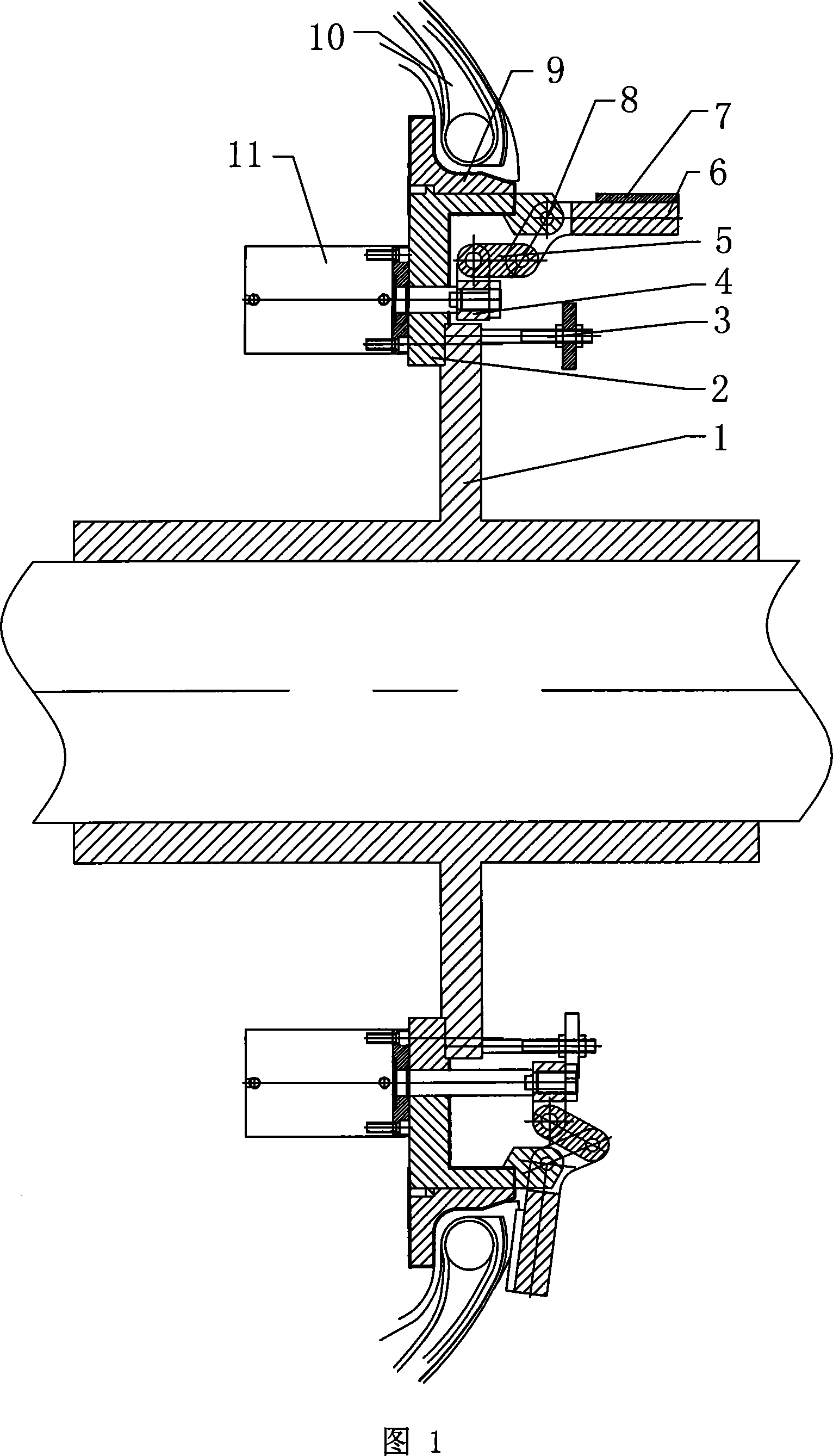
[0016] The embodiment of the traveler locking device of the tire building machine of the present invention is shown in Figure 1. The sliding flange sleeve 1 is installed on the main shaft of the shaping drum of the second section of the tire building machine, and is driven and fixedly connected with the inner shaft screw of the main shaft. The outer positioning table of the flange sleeve 1 is fixedly connected with the inner positioning table of the annular connecting sleeve 2. The outer circumference of the connecting sleeve is evenly fixed with 4 driving cylinders 11, and the connecting sleeve 2 has a through hole matching the driving cylinder 12. The piston rod passes through the hole of the connecting sleeve 2, and is respectively fixed to a push plate 4 inside the connecting sleeve 2. The outer edge of the connecting sleeve 2 is fixed to the easily removable positioning chuck 9, and the stop of the positioning chuck 9 Towards the center of the shaping drum; 4 connecting rods ...


PUM


Abstract

The invention relates to a steel wire ring locking device for the tire building machine, which is characterized in that a slipcover of the sliding flange is sleeved on the main shaft of the boarding drum; the outside of the location platform is fixedly connected with the inner side of the location platform of an annular joint sleeve; a plurality of driving cylinders are evenly distributed on the outside of the joint sleeve; a positioning chuck is fixedly connected with outside edge of the joint sleeve. The cylinder rod of each cylinder passes through the hole of the joint sleeve; a plurality of connecting rods and crank pusher dogs are hinged with the thrusting plate; the turning part of the crank pusher dog is hinged with the transposition of the joint sleeve. The body of the tire tube steel wire ring reaches the location chuck; the driving cylinder simultaneously pushes a plurality of crank pusher dogs of the thrusting plate to swing forth simultaneously; the patulous pressing board lock the steel wire ring tightly on the location chuck. The slipcover of the sliding flange moves inward and takes molding operation. After completion, each cylinder shrinks and drives each crank pusher dog swing inward; the pressing board folds simultaneously and disengages from the steel wire. The slipcover of the sliding flange moves outwards; the steel wire ring separates from the location chuck and the tire can be removed. The invention has the advantages of replacement for the capsule to realize the tightly lock and location of the steel wire ring, high efficiency, better reliability, long service life, few maintenance and favorable quality of the tire.

Description

(1) Technical field [0001] The invention relates to the technology of a tire building machine, in particular to a wire ring locking device of a tire building machine. (2) Background technology [0002] In the current two-stage all-steel tire building machine in the second stage, after the traveller of the carcass tube coming from the first stage building machine reaches the stop of the positioning chuck, the lock of the traveler and the positioning chuck is through the carcass tube The inflation of the capsule is achieved. The capsule is large in size and takes a long time to inflate, and in order to make the carcass tube travellers loaded and aligned, the capsule needs to be inflated and deflated several times during the operation process, and the labor intensity of the workers is high. In particular, the inconsistent stretch of the capsule caused by repeated inflation and deflation affects the symmetry and balance of the tire produced, which is not conducive to improving the qu...

Claims


Application Information

Patent Timeline
IPC IPC(8): B29D30/32
Inventor 钟路强梁国彰汤志盛
Owner GUILIN RUBBER MACHINERY CO LTD
Learn More