Non-aerated solid tyre with damping device
A technology of solid tires and shock absorbing devices, which is applied to wheels, highly elastic wheels, transportation and packaging, etc., can solve problems such as increased use costs, short service life, waste of time and money for car repairs, and achieve enhanced stability and Comfortable, short service life, good shock absorption effect
- Summary
- Abstract
- Description
- Claims
- Application Information
AI Technical Summary
Problems solved by technology
Method used
Image

Examples
Embodiment 1
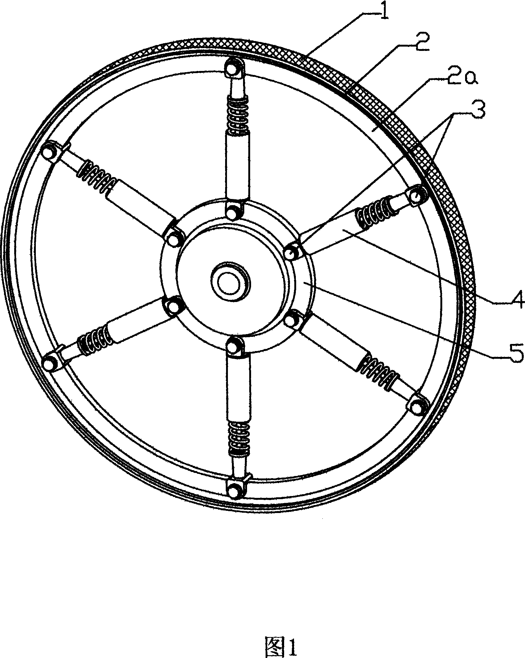
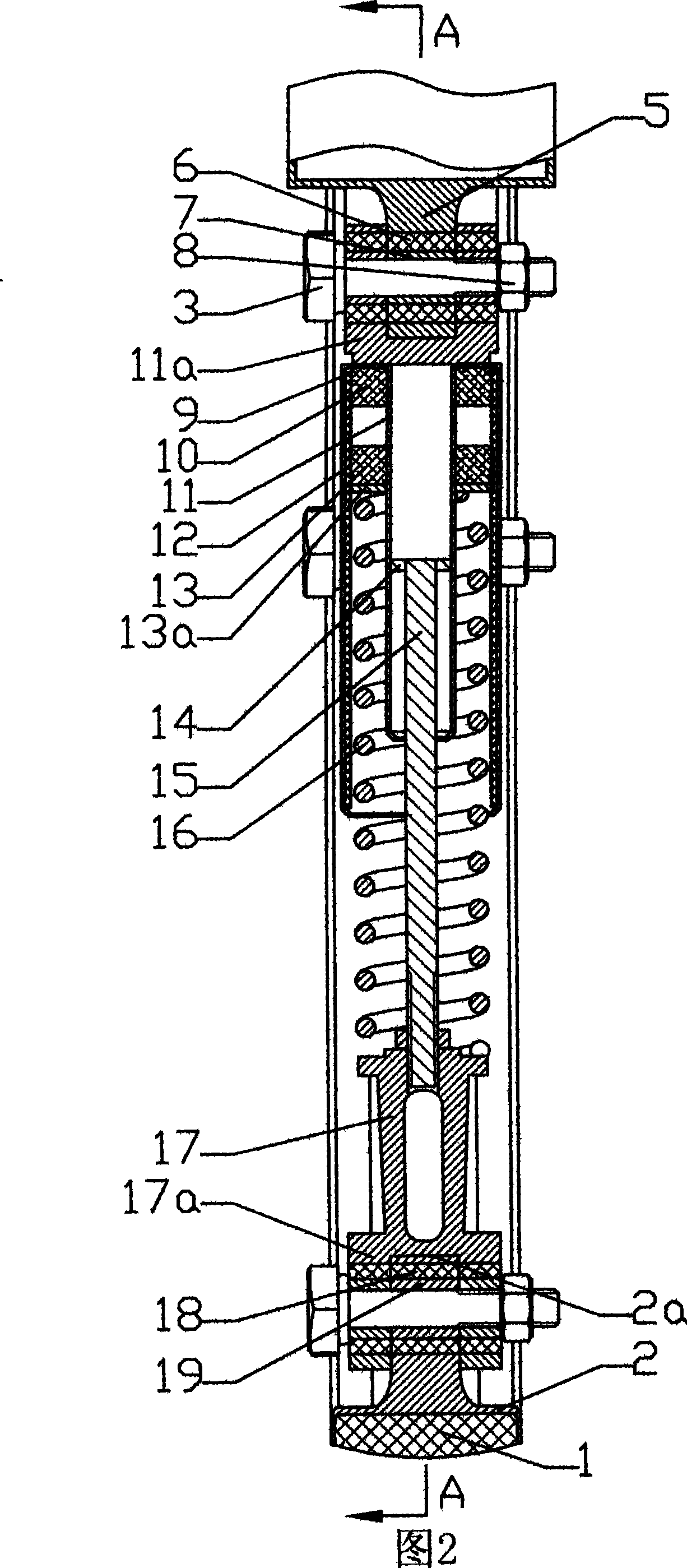
[0018] Embodiment 1 The structure of the non-pneumatic solid tire with shock absorbing device in this embodiment can be seen from Fig. 1, it is a common running wheel of a vehicle, and includes the outer steel ring 2 and the inner steel ring 5 of the coaxial line , a rubber ring 1 is coated on the outer side of the outer steel ring 2, and a plurality of shock absorbers 4 are uniformly arranged between the outer steel ring 2 and the inner steel ring 5, and the two ends of the shock absorber 4 are respectively connected by bolts 3 and nuts 8. Connected on the outer steel ring 2 and the inner steel ring 5.
[0019] The shock absorber 4 is arranged in a circle with 6 or more in total, and a shock absorber 4 is provided with a shock absorber 16 and two opposite magnets of the same pole arranged above the axis of the shock absorber 16, that is, static permanent magnets. Magnet 10 and moving permanent magnet 13, they produce repulsive force, make shock absorber 4 both can stretch and...
Embodiment 2
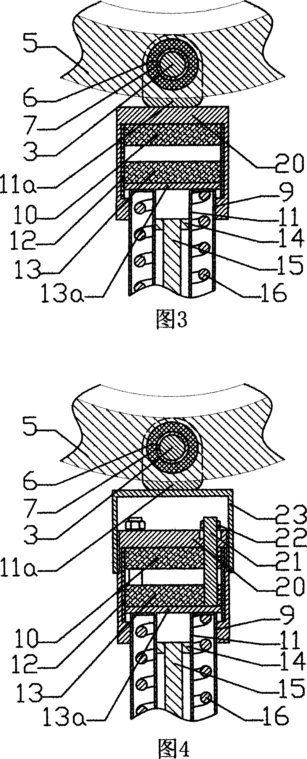
[0027] Embodiment 2 The structure of the non-pneumatic solid tire with the shock absorbing device of this embodiment can be seen from Fig. 3, and it is different from Embodiment 1 in that: the first outer sleeve 9 and the inner steel ring 5 are connected A shock absorbing cavity 20 is installed between the suspension rings 11a, that is, the static permanent magnet 10 and the moving permanent magnet 13 are contained in the shock absorbing cavity 20 instead of directly contacting the shock absorbing spring 16 in the outer sleeve 9 . Now the damping spring 16 is in direct contact with the inner top surface of the outer sleeve 9 .
[0028] As shown in Figure 3, the top surface of the damping cavity 20 is welded and fixed to the first suspension ring 11a connected with the inner steel ring 5, the top of the outer sleeve 9 is inserted into the damping cavity 20, and the top surface of the inner limit sleeve 11 After being integrated with the fixed plate 13a, it is inserted into the ...
Embodiment 3
[0032] Embodiment 3 The air-free solid tire of the band damping device of the present embodiment, its structure can be seen from Fig. 4, and it is different from Embodiment 2 in that: static permanent magnet 10, moving permanent magnet 13 and damping cavity The upper end surface of the body 20 respectively evenly opens 3 through holes and then inserts a magnet guide column 21 respectively.
[0033]As shown in Fig. 4, the bottom of three magnet guide columns 21 is fixed with fixed plate 13a, and promptly stretches out shock absorbing cavity 20 ends and twists a limit nut 22 at its top, makes magnet guide column 21 follow-up permanently The magnet 13 moves up and down, and because the stop nut 22 cannot pass through the through hole, it is more guaranteed that it will not escape from the upper end surface of the shock absorbing cavity 20 when it moves, which is more conducive to the up and down movement of the magnet without tilting. Screw a nut cover 23 on the top of the dampin...
PUM
 Abstract
Description
Claims
Application Information
 - Generate Ideas
- Intellectual Property
- Life Sciences
- Materials
- Tech Scout
- Unparalleled Data Quality
- Higher Quality Content
- 60% Fewer Hallucinations
Browse by: Latest US Patents, China's latest patents, Technical Efficacy Thesaurus, Application Domain, Technology Topic, Popular Technical Reports.
© 2025 PatSnap. All rights reserved.Legal|Privacy policy|Modern Slavery Act Transparency Statement|Sitemap|About US| Contact US: help@patsnap.com