Coreless wire coil precise winding machine

A winding machine, precise technology, applied in the direction of conveying filamentous materials, thin material handling, transportation and packaging, etc., can solve the problems of low accuracy, increase production costs, occupy the user's production site, etc., to achieve accurate tracking, The effect of saving production costs and improving accuracy

Inactive Publication Date: 2008-05-14
关著铭
View PDF0 Cites 23 Cited by
  • Summary
  • Abstract
  • Description
  • Claims
  • Application Information

AI Technical Summary

Problems solved by technology

This way of operation, on the one hand, users need to purchase special disks in large quantities, which increases production costs; moreover, these special disks need to be recycled, which increases the user's round-trip transportation costs and production operation costs, and at the same time occupies a large number of users' production sites
[0003] In addition, the existing winding machines mainly use polished rods or screw rods. For polished rods, the pitch of the wires is manually adjusted. The accuracy is low, and it is difficult to adjust the pitch of the wires to the winding pitch. The wire diameter is the same; the two outer wires track and take up the wires through mechanical transmission. When the distance between the wires and the wires is far away, the mechanical transmission structure is complicated.
The traditional screw cable is driven by an independent motor, and the pitch of the cable is not easy to control. Usually, the cable motor is used to track the speed of the take-up motor, which cannot achieve precise tracking and close arrangement of lines.
Since the above-mentioned wire arrangement method cannot realize precise tracking and tight wire take-up, it is not suitable for some occasions or products that have high requirements for cable arrangement, such as strip wire arrangement, tight take-up, etc.

Method used


Image

  • Coreless wire coil precise winding machine
  • Coreless wire coil precise winding machine
  • Coreless wire coil precise winding machine

Examples


Embodiment Construction

[0026] The present invention will be further described below in conjunction with the accompanying drawings and embodiments.

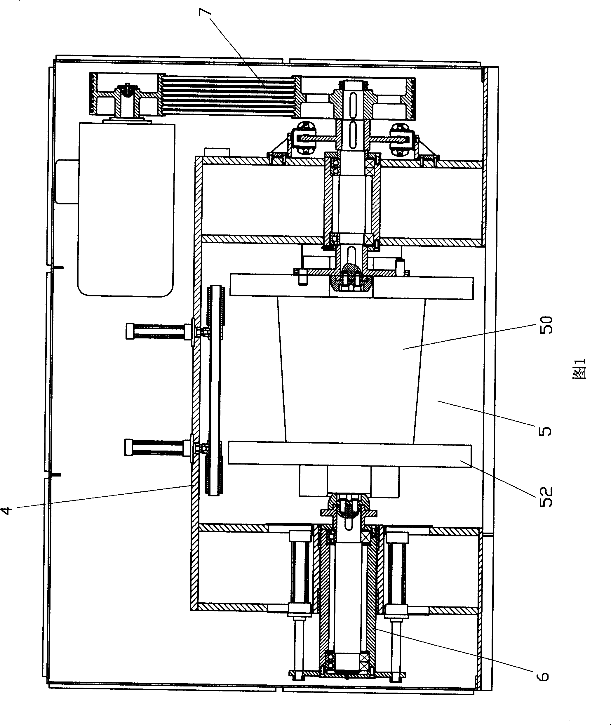
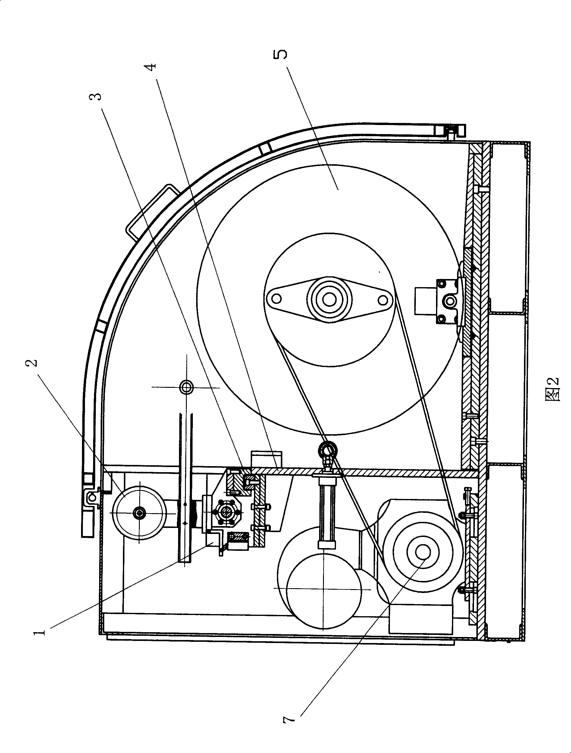
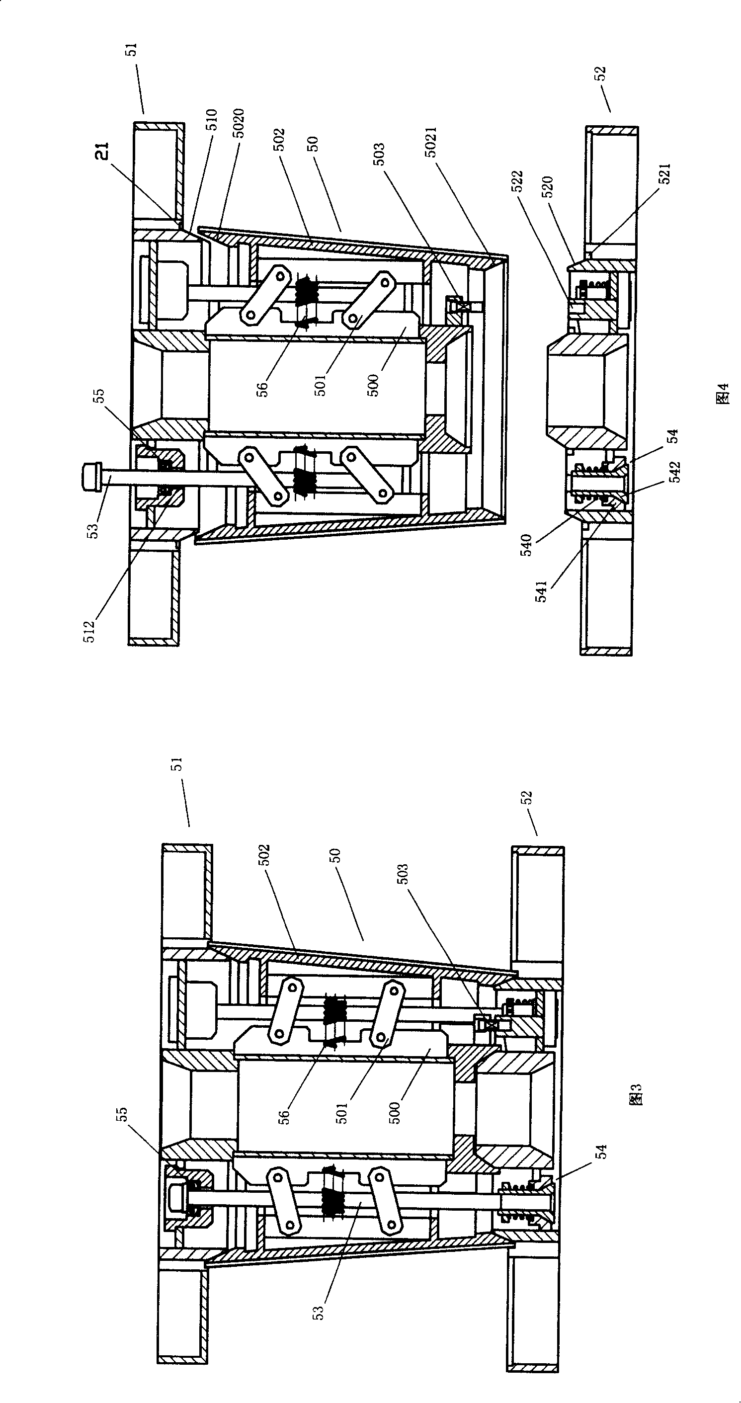
[0027] Referring to Fig. 1 to Fig. 2, a precision winding machine without a core wire reel includes a wire arrangement device and a winding device; the winding device includes a wire reel 5, a clamping device 6 and a driving device 7, and the driving device 7 Drive the wire reel 5 clamped by the clamping device 6 to rotate; the wire reel 5 is provided with an expandable conical shaft core 50, and the second flange 52 on the smaller side of the conical shaft core cross-section and the cone Shaft core 50 is detachably connected. After the finished wire rod is processed, the clamping device 6 releases the wire reel 5, and the wire reel 5 can be disassembled to separate it from the finished wire rod. The finished wire can be handed over to the follow-up users after simple packaging, without occupying the tray, saving production costs and follow-up support ...


PUM


Abstract

The invention relates to a winding machine without core wire coil, which comprises a wire arrangement device and a wire winding device; wherein, the wire arrangement device comprises a movable coil holder and a guide wheel to arrange the wires; the guide wheel to arrange the wires is arranged on the movable coil holder connected with the frame of the winding machine through a linear guide; the wire winding device comprises a wire coil, a clamp device and a drive device; wherein the drive device drives the wire coil which is clamped by the clamp device to rotate. The invention is characterized in that an expanding conical spindle is arranged for the wire coil; a second flange at one side of the smaller cross section of the conical shaft core is connected with the conical shaft core in a demountable method. The invention has the advantages that the imbibed conical shaft core can be demounted from the wire coil after produced from the processed product wire and can be delivered to follow-up users through simply packaging without occupying the coil tool, thereby saving production cost and consumption cost supported by follow-up users.

Description

Technical field [0001] The invention relates to winding machines used in the production industries of electric wires and cables, optical cables, steel wires, etc., and in particular relates to a coreless coil winding machine. Background technique [0002] At present, the winding machines used in the wire and cable, optical cable, steel wire and other production industries generally use non-detachable iron I-shaped machine reels or frame-type hurdles as special production reels, and the finished wire products produced need to be the same as the special reels. sent to subsequent users together. This way of operation, on the one hand, users need to purchase special disks in large quantities, which increases production costs; moreover, these special disks need to be recycled, which increases the user's round-trip transportation costs and production operation costs, and simultaneously occupies a large number of users' production sites. [0003] In addition, the existing winding ...

Claims


Application Information

Patent Timeline
Patent Type & Authority Applications(China)
IPC IPC(8): B65H54/02B65H75/24B65H51/30B65H51/18
Inventor 关著铭张杰
Owner 关著铭
Why Eureka
Try Eureka